
Engine and pressure testing mechanism thereof

An engine and pressure measurement technology, which is applied to engine components, machines/engines, mechanical equipment, etc., can solve problems such as miscontrol, failure to obtain the operating status of the pressure sensor, and pressure sensor detection

Pending Publication Date: 2019-11-01
JIANGMEN DACHANGJIANG GROUP CO LTD
View PDF0 Cites 0 Cited by
  • Summary
  • Abstract
  • Description
  • Claims
  • Application Information

AI Technical Summary

Problems solved by technology

However, the traditional engine cannot detect the pressure sensor at the throttle body, and cannot obtain the operating condition of the pressure sensor itself. Therefore, once the pressure sensor fails, the operating condition of the pressure sensor cannot be obtained in time, which is easy Misjudgment and miscontrol of engine operating conditions
Therefore, the traditional pressure measuring mechanism cannot meet the requirements of the second-generation on-board diagnostic system

Method used


Image

  • Engine and pressure testing mechanism thereof
  • Engine and pressure testing mechanism thereof
  • Engine and pressure testing mechanism thereof

Examples


Embodiment Construction

[0025] In order to make the object, technical solution and advantages of the present invention clearer, the present invention will be further described in detail below in conjunction with the accompanying drawings and specific implementation methods. It should be understood that the specific embodiments described here are only used to explain the present invention, and do not limit the protection scope of the present invention.

[0026] It should be noted that when an element is referred to as being “fixed” to another element, it can be directly on the other element or there can also be an intervening element. When an element is referred to as being "connected to" another element, it can be directly connected to the other element or intervening elements may also be present. The terms "vertical," "horizontal," "left," "right," and similar expressions are used herein for purposes of illustration only and are not intended to represent the only embodiments.

[0027] Unless otherw...


PUM


Abstract

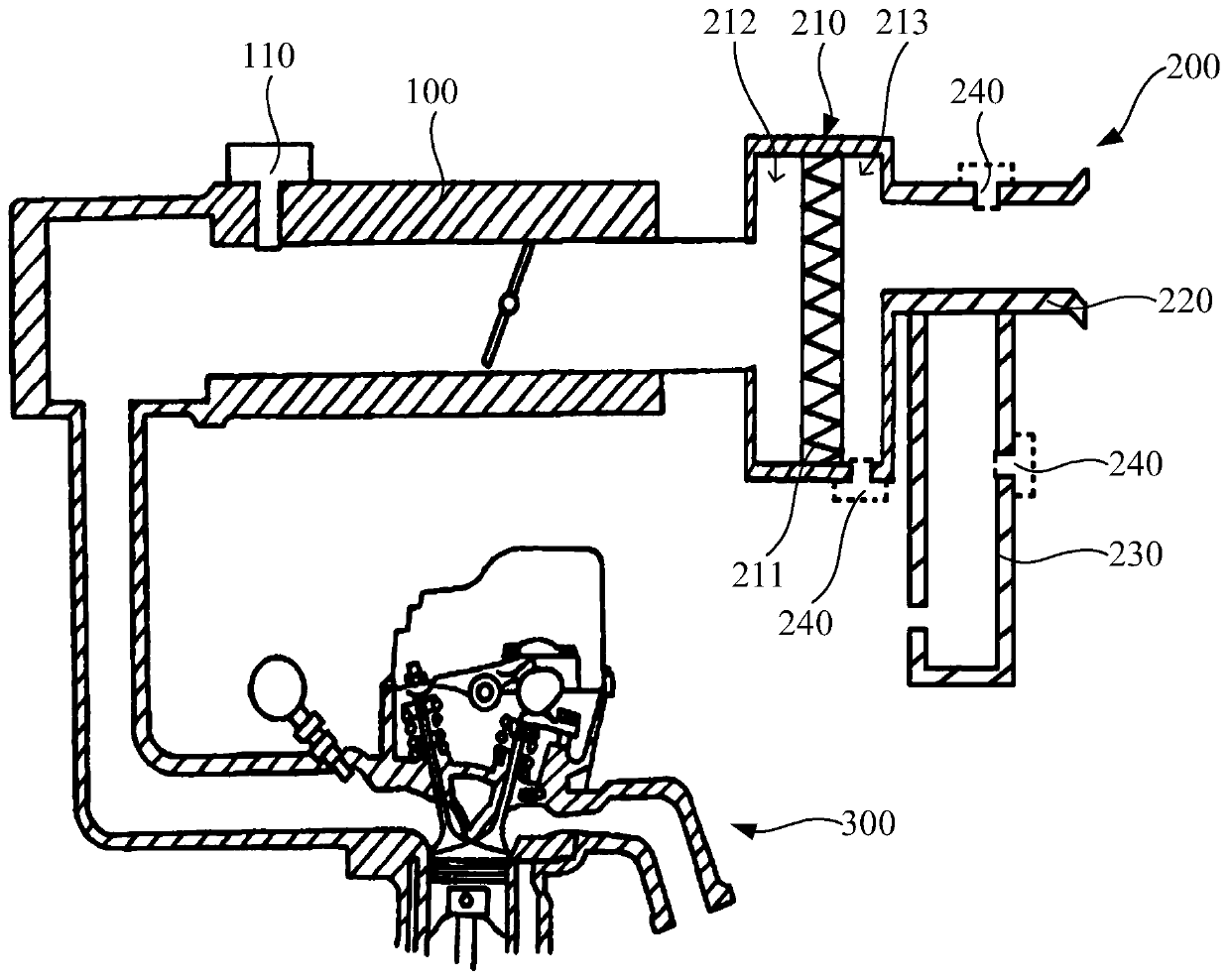
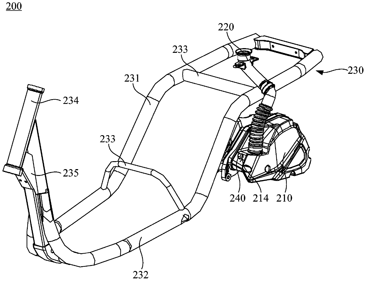
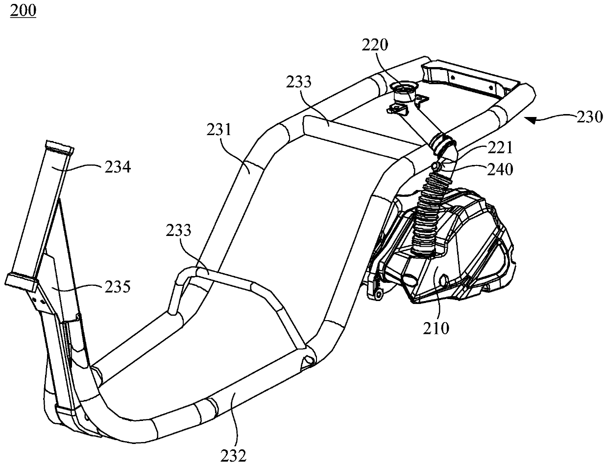
The invention discloses an engine and a pressure testing mechanism thereof. A first pressure sensor and a second pressure sensor are arranged on a throttle valve body and a mounting structure correspondingly. Through the first pressure sensor, air inlet pressure in the throttle valve body is obtained; and through the second pressure sensor, the atmospheric pressure is obtained. Before the engine is started, the pressure in the throttle valve body is equal or similar to the atmospheric pressure, at this moment, the first pressure sensor and the second pressure sensor are used jointly, and pressure values of the two pressure sensors are compared. According to comparison results of the first pressure sensor and the second pressure sensor, operating conditions of the first pressure sensor areobtained in time. If the pressure value obtained through the first pressure sensor is equal to or similar to that obtained through the second pressure sensor, it is judged that the first pressure sensor operates normally; and followingly, the operating conditions of the engine are further accurately judged.

Description

technical field [0001] The invention relates to the technical field of engines, in particular to an engine and a pressure measuring mechanism thereof. Background technique [0002] When the engine starts, the throttle body opens, and the gas enters the engine cylinder through the throttle body, and mixes with gasoline to form a combustible mixture; under the action of the igniter, it burns and works on the piston. In a traditional engine, a pressure sensor is usually installed at the throttle body to detect the intake air pressure at the throttle body, so as to judge the operating condition of the engine and the fuel injection quantity and other related controls. However, the traditional engine cannot detect the pressure sensor at the throttle body, and cannot obtain the operating condition of the pressure sensor itself. Therefore, once the pressure sensor fails, the operating condition of the pressure sensor cannot be obtained in time, which is easy Misjudgment and miscont...

Claims


Application Information

Patent Timeline
Patent Type & Authority Applications(China)
IPC IPC(8): F02M35/10F02M35/16F02M37/32G01L23/24
CPCF02M35/10006F02M35/1038F02M35/16F02M37/32G01L23/24
Inventor 余华荣叶晓明
Owner JIANGMEN DACHANGJIANG GROUP CO LTD
Learn More