Check valve

A technology for check valves and valve bodies, applied in valve details, control valves, valve devices, etc., can solve the problems of reduced service life of check valves, high medium pressure, excessive impact of disc or valve core, etc., to reduce Shock, the effect of increasing the service life

Active Publication Date: 2019-11-01
JIANGSU SHENGTAI VALVE CO LTD
View PDF9 Cites 1 Cited by
  • Summary
  • Abstract
  • Description
  • Claims
  • Application Information

AI Technical Summary

Problems solved by technology

[0002] At present, the commonly used check valves are swing check valve (rotating according to the center of gravity) and lift check valve (moving along the axis), but due to the existence of the valve disc or the valve core, when the medium passes through the check valve, the pressure The drop is serious, and the flow rate is reduced; and because the movement of the valve disc or the valve core directly depends on the pressure difference between the two sides of the medium, there is too much impact on the valve disc or the valve core, which reduces the service life of the check valve. Return valve (moving along the axis) Since the projection surface of the medium in the moving direction of the valve is large, the pressure of the medium that the valve needs to overcome during the movement is also large

Method used


Image

  • Check valve
  • Check valve
  • Check valve

Examples


Embodiment Construction

[0024] The preferred embodiments of the present invention will be described below in conjunction with the accompanying drawings. It should be understood that the preferred embodiments described here are only used to illustrate and explain the present invention, and are not intended to limit the present invention.

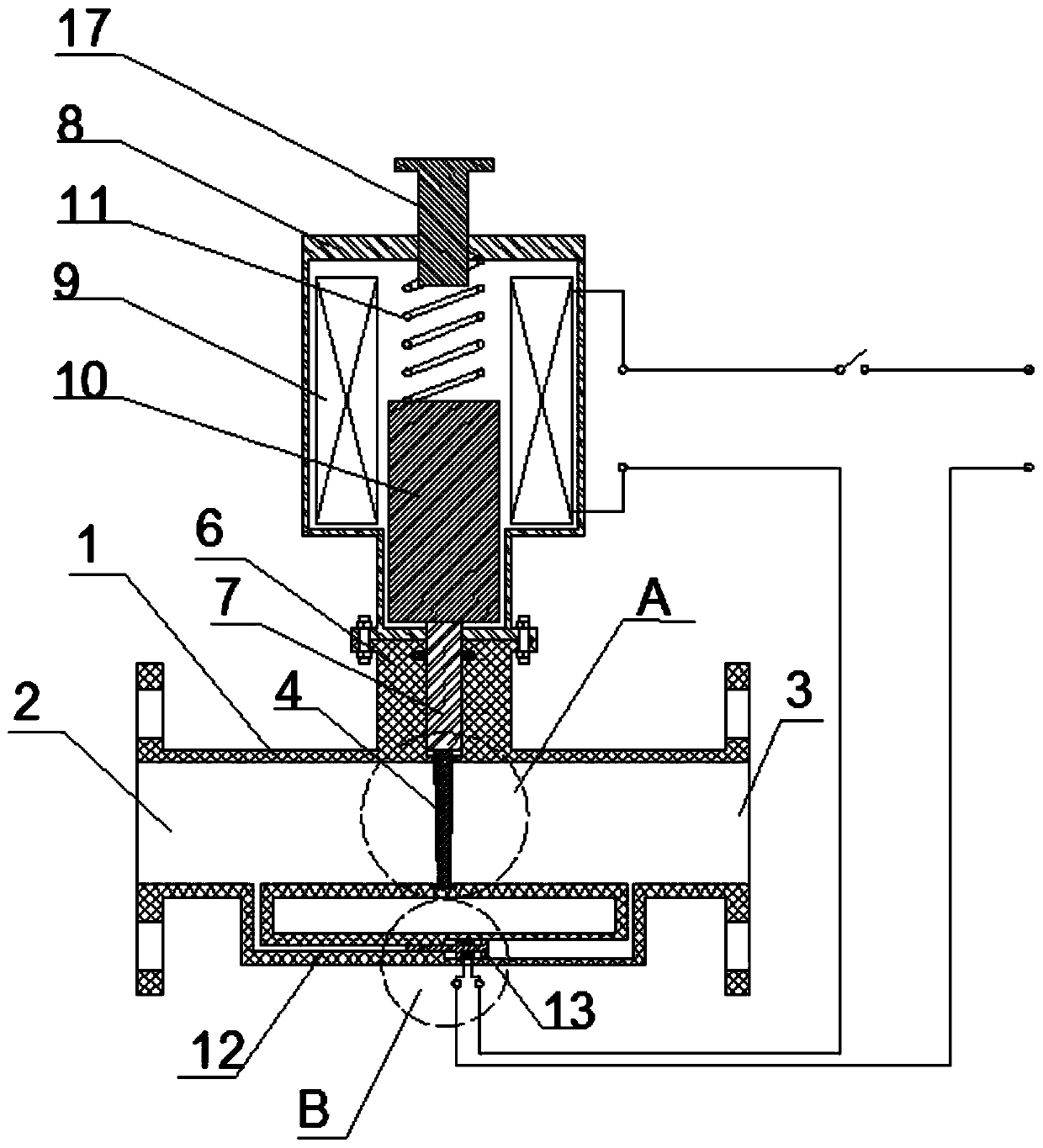
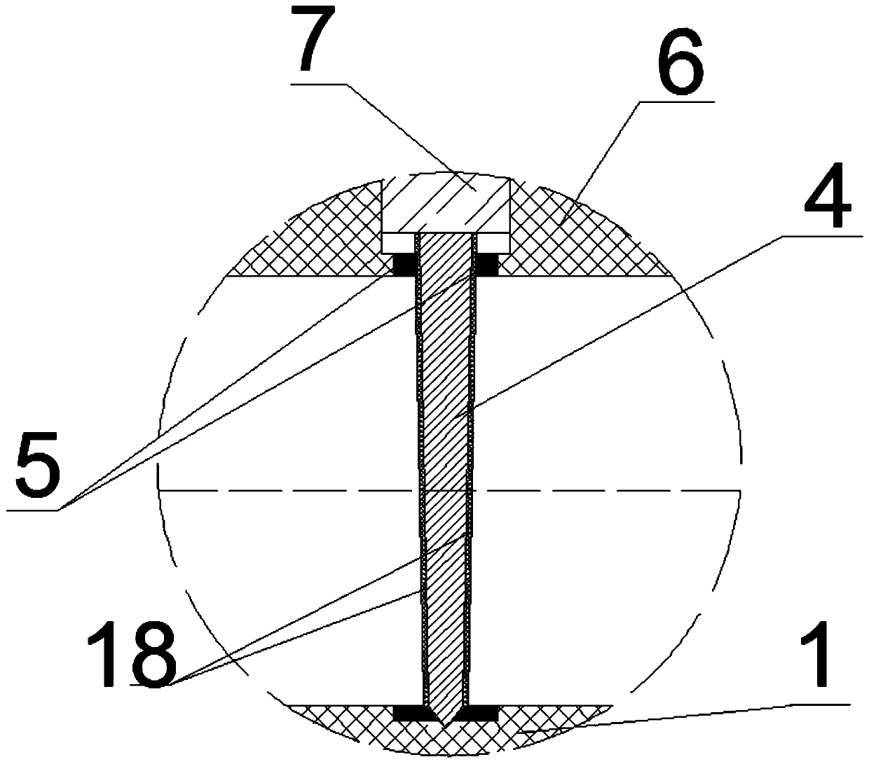
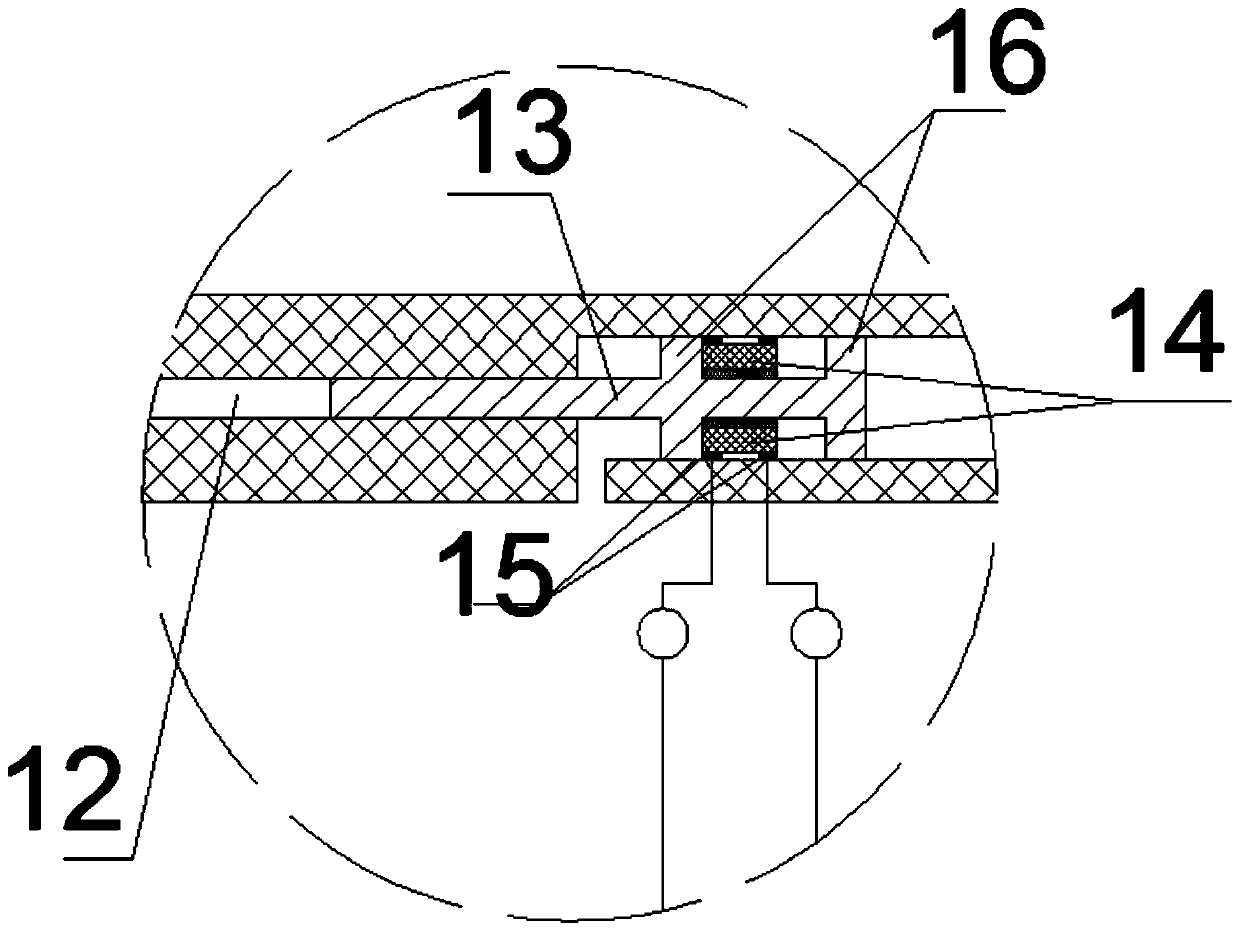
[0025] The invention provides a check valve, such as figure 1 , figure 2 , image 3 As shown, it specifically includes: a valve body assembly, the two ends of the valve body body 1 of the valve body assembly are respectively provided with a valve body inlet 2 and a valve body outlet 3; a valve disc 4 is provided in the middle of the valve body body, and the valve The flap is an inverted trapezoid; both sides of the valve flap 4 are provided with valve seats 5; the upper end of the middle part of the valve body 1 is provided with a connecting pipe 6; the connecting pipe 6 is provided with a push rod 7, and the push rod 7 It is sealed and slidable with the side wal...


PUM


Abstract

The invention provides a check valve. The check valve is characterized by comprising a valve body assembly, an electromagnetic assembly and a diversion assembly, wherein the valve body assembly is provided with a valve flap, a valve seat, a connecting pipe and a push rod, the valve flap is shaped like an inverted trapezoid, and the lower end of the push rod is connected with the upper end of the valve flap; the outer wall of the electromagnetic assembly is connected with the connecting pipe, and a coil, a movable iron core and a spring are arranged in the outer wall of the electromagnetic assembly; a sliding block is arranged in a diversion pipeline of the diversion assembly, conductive blocks are arranged on the sliding block, two conductive contact points are arranged in the diversion pipeline, and the conductive blocks enable the two conductive contact points to be connected or disconnected; and the two conductive contact points are connected with the coil, a power supply and a circuit switch in series. According to the check valve, the valve flap can be completely pulled out of a medium between a valve body inlet and a valve body outlet, so that when the check valve is connected, the pressure and the flow of the medium cannot be affected, and the check valve can be used for the situation with large flow; and meanwhile, the impact of the medium to the valve flap and abrasionbetween the valve flap and a valve body are reduced, and the service life of the check valve is prolonged.

Description

technical field [0001] The invention relates to the technical field of valves, in particular to a check valve. Background technique [0002] At present, the commonly used check valves are swing check valve (rotating according to the center of gravity) and lift check valve (moving along the axis), but due to the existence of the valve disc or the valve core, when the medium passes through the check valve, the pressure The drop is serious, and the flow rate is reduced; and because the movement of the valve disc or the valve core directly depends on the pressure difference between the two sides of the medium, there is too much impact on the valve disc or the valve core, which reduces the service life of the check valve. Back valve (moving along the axis) has a large projection surface of the medium in the moving direction of the valve, so the pressure of the medium that the valve needs to overcome during the movement is also large. Contents of the invention [0003] In order...

Claims


Application Information

Patent Timeline
Patent Type & Authority Applications(China)
IPC IPC(8): F16K15/18F16K15/06F16K31/06
CPCF16K15/06F16K15/18F16K31/0655F16K31/0675
Inventor 严涛丁超果春焕史可任王金鹤李伟
Owner JIANGSU SHENGTAI VALVE CO LTD
Why Eureka
Try Eureka