
Meridian comb

A meridian and comb technology, applied in the field of meridian combs, can solve problems such as hair knotting and single function of the comb

Pending Publication Date: 2019-11-05
上海回初科技有限公司
View PDF0 Cites 0 Cited by
  • Summary
  • Abstract
  • Description
  • Claims
  • Application Information

AI Technical Summary

Problems solved by technology

[0004] Aiming at the problems of single function of the comb in the prior art and prone to hair knotting during use, the purpose of the present invention is to provide a comb for meridians

Method used


Image

  • Meridian comb
  • Meridian comb
  • Meridian comb

Examples


Embodiment 1

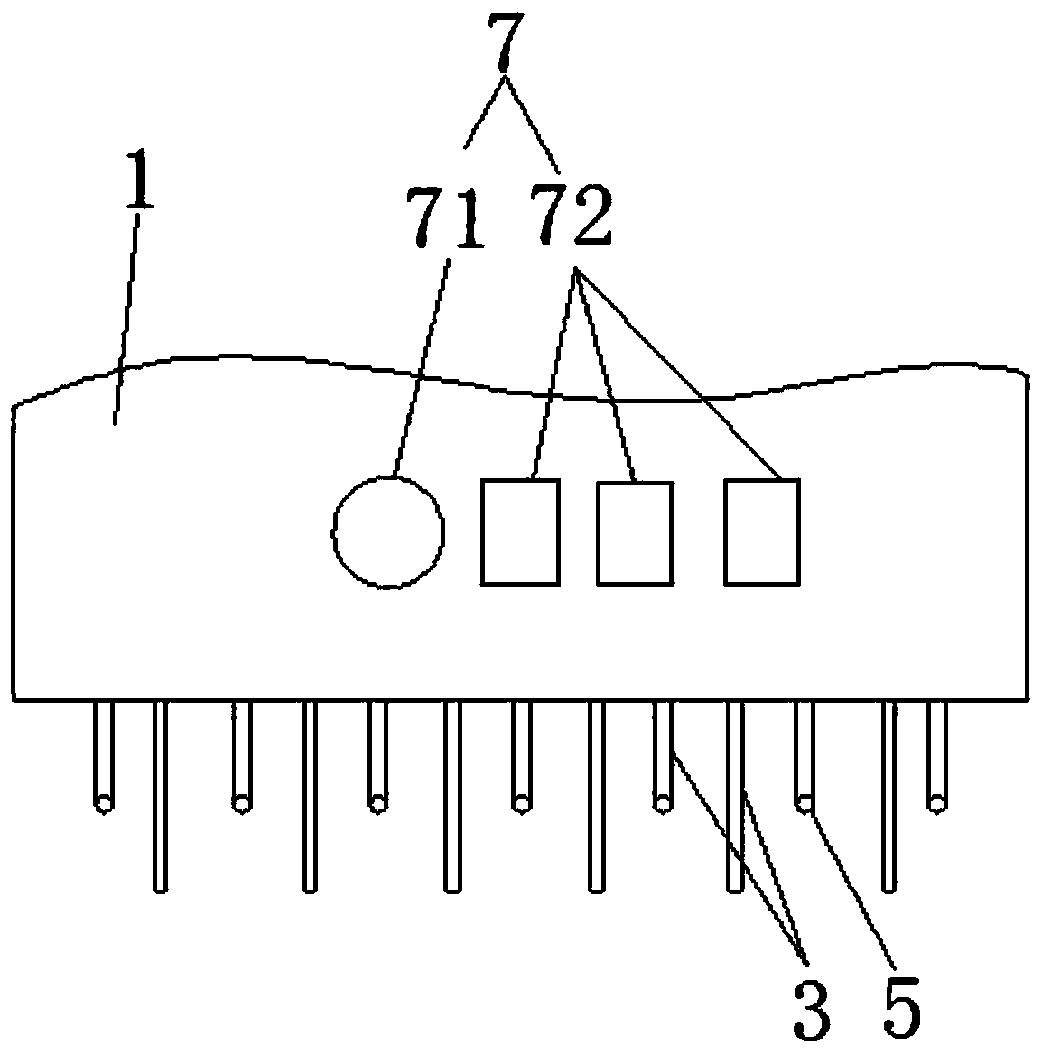
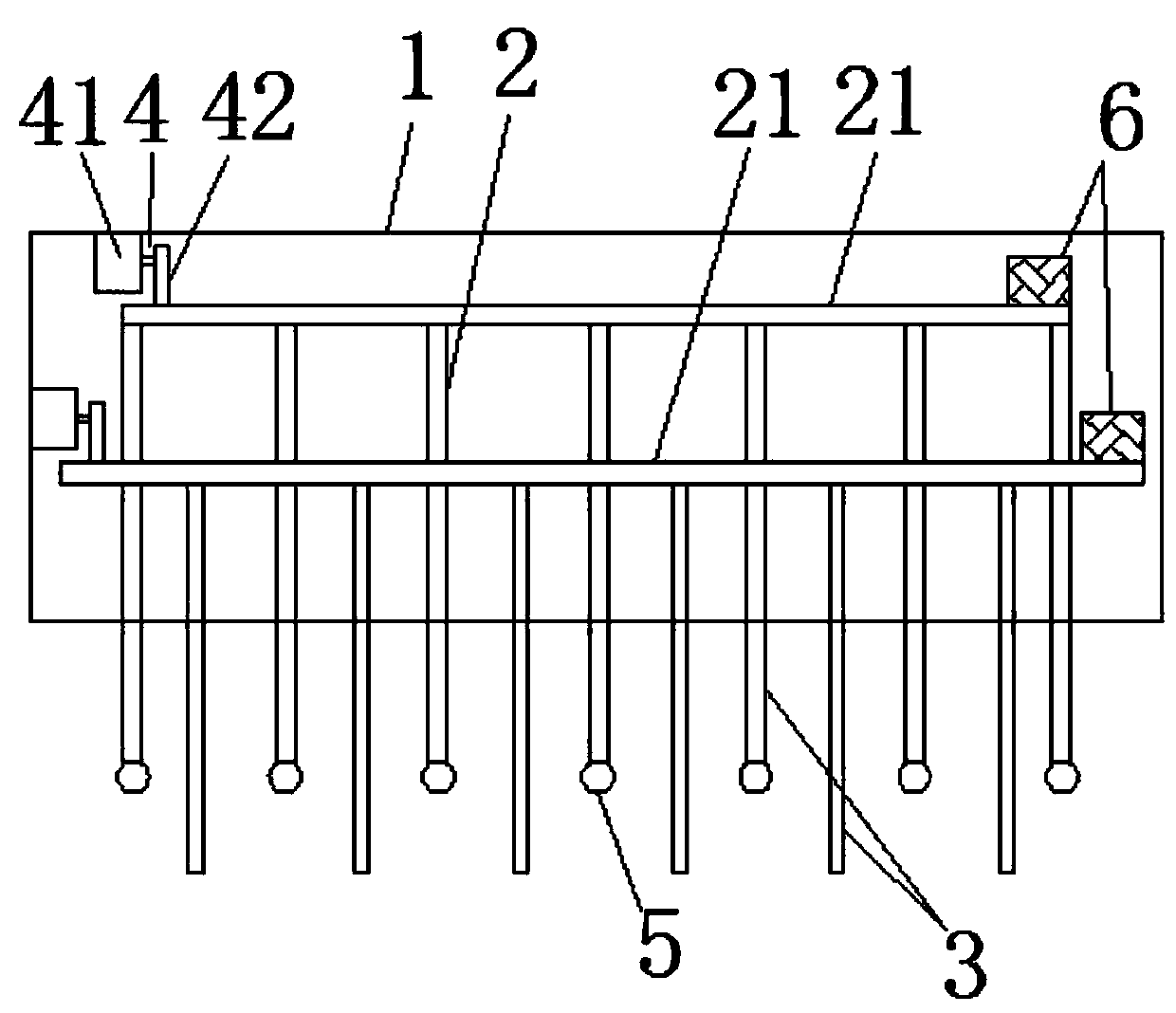
[0024] Such as figure 1 , figure 2 Shown, a kind of meridian comb, comprises comb body 1, and comb body 1 is used for gripping, and its surface is a curved surface, and the shape is adapted to the shape of people's palm when holding an object; Comb body 1 is installed with at least two There are two movable comb assemblies 2 in this embodiment; of course, in another embodiment, the number of movable comb assemblies 2 can be three or four.

[0025] The movable comb assembly 2 includes a comb mounting part 21 slidably connected to the comb body 1, a sliding drive device 4 fixedly connected to the comb body 1, and several comb teeth 3 arranged on the comb mounting part 21. The sliding direction of the component 21 is parallel to the comb teeth 3, and the sliding drive device 4 is used to drive the comb tooth mounting part 21 to reciprocate; In the same plane, that is, when the comb-tooth mounting part 21 is carrying the comb-teeth 3 to move, the positions of the ends of the co...

Embodiment 2

[0043] The difference from Embodiment 1 is that instead, the sliding drive device 4 includes a sliding motor 41, which is connected to the comb mounting part 21 through a crank linkage mechanism, thereby driving the comb mounting part 21 to reciprocate.

Embodiment 3

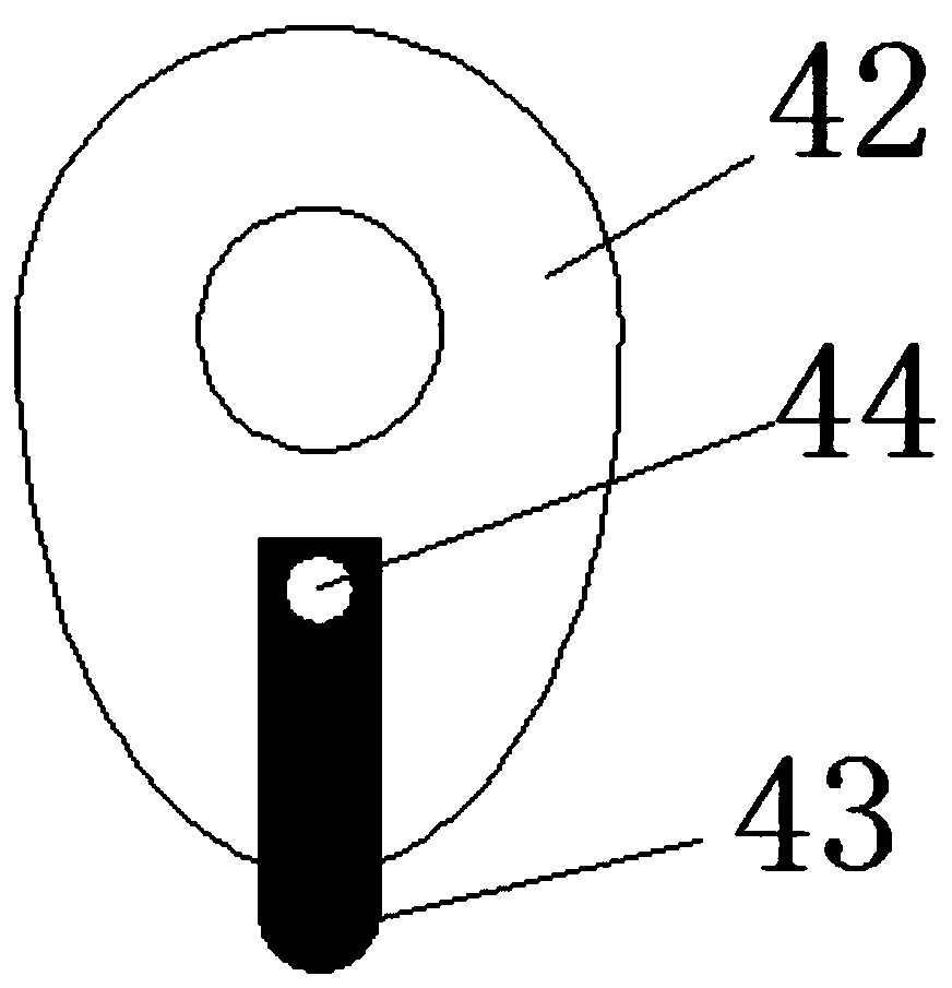
[0045] On the basis of Embodiment 1, in order to meet the different needs of different groups of people for pressing force requirements, in this embodiment, an adjustment bump 43 is installed on the end surface of the cam 42, and the adjustment bump 43 is movably connected with the cam 42. The movable track of the free end of the protruding block 43 protrudes from the top of the cam 42. When it is necessary to adjust the farthest distance from the free end of the comb teeth 3 to the comb body 1, it is only necessary to adjust the protruding block 43 so that its free end is positioned at the other end of the protruding cam 42 top. position, and then fix the adjustment bump 43 by locking screws, as image 3 Shown is a schematic diagram when the adjustment lug 43 is rotationally connected with the cam 42 through the pin shaft 44 . Or, make adjustment projection 43 and cam 2 slide connection, as Figure 4 Shown is a schematic diagram of the sliding connection between the adjustme...


PUM


Abstract

The invention discloses a meridian comb, and belongs to the field of daily necessities. The meridian comb comprises a comb body, at least two movable comb assemblies are installed on the comb body, the movable comb assemblies comprise comb installation parts slidably connected with the comb body, a plurality of combs arranged on the comb installation parts and sliding driving devices fixed to thecomb body, the sliding direction of the comb installation parts is parallel to the combs, and the sliding driving devices are used for driving the comb installation parts to move back and forth; and the farthest points of the free ends of the combs in the at least two movable comb assemblies from the comb body are not in the same plane. According to the meridian comb, the design is reasonable, thestructure is simple, the hair can be effectively prevented from knotting when combing, and the function of massaging scalp meridians is further achieved.

Description

technical field [0001] The invention relates to the field of daily necessities, in particular to a meridian comb. Background technique [0002] A comb is a tool for combing hair, and usually includes a comb body that is convenient for the user to hold and comb teeth installed on the comb body. Along with people more and more higher to the requirement of quality of daily life, the comb that can only comb hair with single function can't satisfy needs. [0003] For example, the comb teeth on the existing comb cannot move, and the length of the comb teeth is basically the same, so the hair cannot be combed layer by layer. Too much entangled hair will cause the hair to become knotted and entangled, which will cause inconvenience to combing the hair. Contents of the invention [0004] Aiming at the problems in the prior art that the comb has single function and the hair tends to get tangled during use, the purpose of the present invention is to provide a meridian comb. [000...

Claims


Application Information

Patent Timeline
IPC IPC(8): A61H11/00A61H15/00A61H23/02
CPCA61H11/00A61H15/00A61H23/02A61H2015/0042A61H2201/1207A61H2205/021
Inventor 聂佳伦
Owner 上海回初科技有限公司
Learn More