[0022] The specific implementation manners of the present invention will be further described in detail below in conjunction with the accompanying drawings.
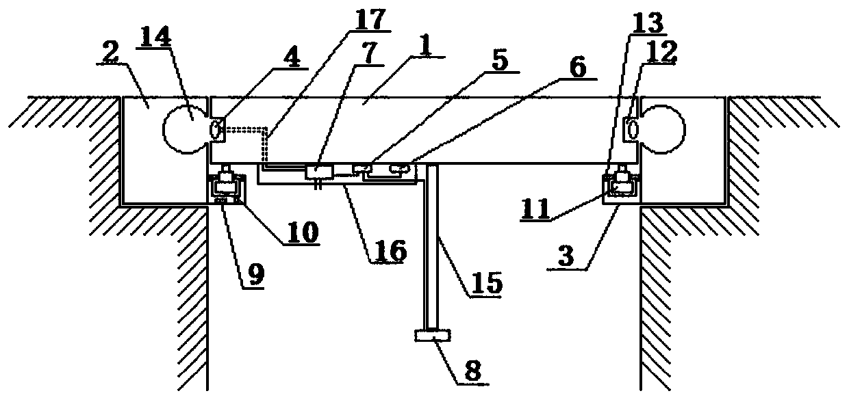
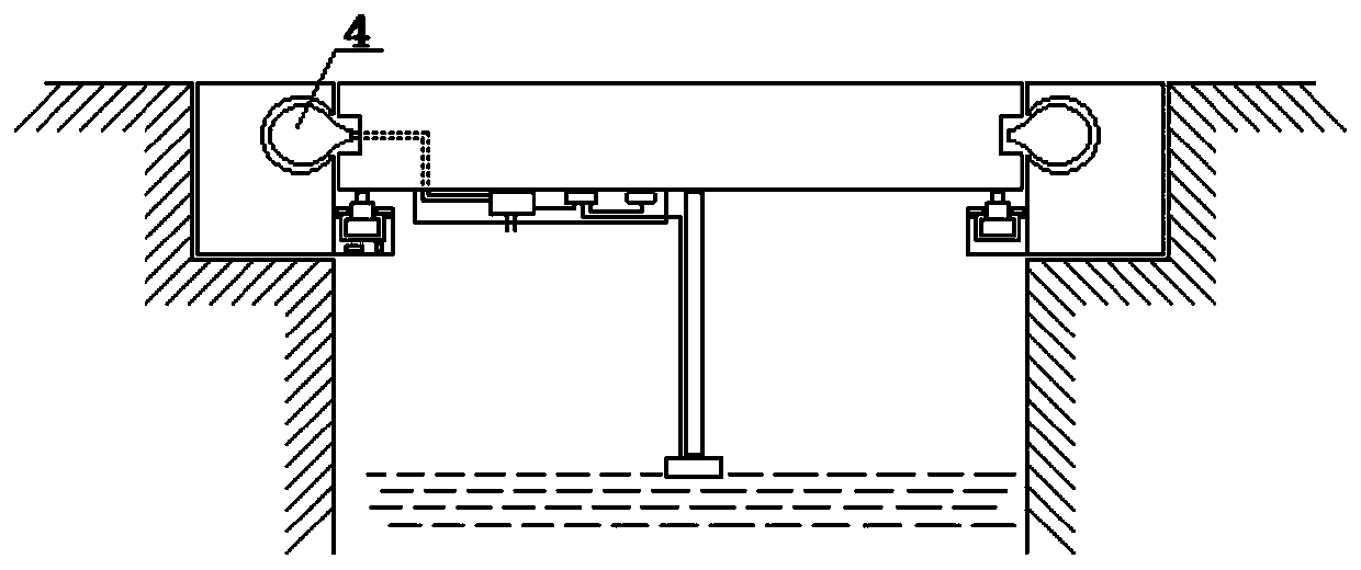
[0023] The present invention designs a kind of anti-theft and anti-surge manhole cover device of air bag locking type, such as figure 1As shown, it includes a manhole cover body 1, an outer barrel body 2, an edge barrel body 3, an air bag 4, a first control module 5, a self-contained power supply 6, a micro air pump 7, a water immersion sensor 8, a second control module 9, and a communication module 10 and at least three miniature electronically controlled telescopic rods 11; wherein, the first control module 5 is connected to the self-contained power supply 6, the miniature air pump 7, and the water immersion sensor 8 respectively, and the second control module 9 is connected to the communication module 10 and each The miniature electronically controlled expansion rod 11 is connected; Self-contained power supply 6 supplies power for micro air pump 7 and water immersion sensor 8 respectively through first control module 5; Wherein, the surface of well cover body 1 is circular, and the top surface of well cover body 1, The bottom surfaces are all flat, and the manhole cover body 1 is a permeable concrete integrally formed structure. The manhole cover body 1 is provided with a base groove 12 surrounding the side; the airbag 4 is a ring-shaped airbag connected end to end. The minimum outer diameter of the inner wall of the base groove 12 on the side of the well cover body 1 is adapted, the annular air bag 4 is sleeved in the base groove 12 on the side of the well cover body 1, the first control module 5, the self-contained power supply 6 and the micro air pump 7 are fixed Set on the bottom surface of the well cover body 1, the working air nozzle of the micro air pump 7 is connected to the annular air bag 4 through the air guide tube 17, and the air guide tube 17 is arranged inside the well cover body 1, and the micro air pump 7 is controlled by the first control module 5. The working air nozzle performs inflation and deflation operations for the annular airbag 4, and when the micro air pump 7 is not inflated, the micro air pump 7 is placed inside the base groove 12 and does not protrude from the notch of the base groove 12; the water immersion sensor 8 is suspended at the preset height position below the bottom surface of the well cover body 1; the outer diameter of the well cover body 1 is compatible with the inner diameter of the outer barrel body 2; The caliber of the vertical shaft opening is compatible; the outer barrel body 2 is horizontally embedded and fixedly arranged on the ground at a position corresponding to the underground vertical shaft opening. The opening of the bottom surface of the barrel body 2 is connected to the underground vertical well mouth; the two ends of the barrel body 3 along the mouth are open and communicate with each other, the outer diameter of the barrel body 3 is compatible with the inner diameter of the outer barrel body 2, and the barrel body 3 along the mouth is fixed. Embedded inside the outer barrel body 2, the outer wall of the mouth barrel body 3 is fixedly connected with the inner wall of the outer barrel body 2, and the center line of the mouth barrel body 3 is collinear with the center line of the outer barrel body 2; The height of the top opening of the barrel body 3 along the mouth is lower than the height of the opening of the top surface of the outer barrel body 2, and the difference between the height of the opening of the top surface of the barrel body 3 along the mouth and the height of the opening of the top surface of the outer barrel body 2 greater than the thickness of the well cover body 1; the difference between the outer diameter and the inner diameter of the barrel body 3 along the mouth is greater than the outer diameter projected along the direction of the micro-electrically controlled telescopic rod 11, and the motors of each micro-electrically controlled telescopic rod 11 are respectively fixed inside Embedded on the surface around the edge of the open opening at the top of the mouth barrel body 3, and the lengths of the connecting lines between the adjacent miniature electronically controlled telescopic rods 11 are equal to each other, and the motors of each miniature electronically controlled telescopic rod 11 are located at the positions where they are located. In the inside of the surface, cover plates 13 are respectively fixed at the groove openings at the positions of the motors on each miniature electronically controlled telescopic rod 11, and cover plates 13 are respectively arranged to run through it up and down. The through hole on the surface, the inner diameter of the through hole is compatible with the outer diameter of the telescopic rod on the miniature electric control telescopic rod 11, and the telescopic rod on each micro electric control telescopic rod 11 passes through the through hole on the corresponding cover plate 13 vertically upwards respectively The second control module 9 and the communication module 10 are arranged in the interlayer between the inner wall and the outer wall of the barrel body 3 along the mouth; the second control module 9 is connected to the municipal power supply network to take power, respectively, the communication module 10, and each micro electric control The telescoping rod 11 supplies power; the motor heights of each miniature electronically controlled telescopic rod 11 are identical to each other, and each miniature electronically controlled telescopic rod 11 works synchronously under the control of the second control module 9. The heights of the tops are the same; when the telescopic rods on the miniature electronically controlled telescopic rods 11 are at the shortest length, the well cover body 1 is detachable and horizontally placed in the top opening of the outer barrel body 2, and the surface where the top surface of the well cover body 1 is located is in contact with the outer barrel body. 2. The surfaces where the top openings are located are in the same plane. The tops of the telescopic rods on the miniature electric control telescopic rods 11 are in contact with the edge of the bottom surface of the manhole cover body 1. Rising; the inner wall of the outer barrel body 2 is higher than the outer barrel body 3, and the locking groove 14 is set on the circumference of the outer barrel body 3. Based on the fact that the telescopic rods on each micro-electrically controlled telescopic rod 11 are at the shortest length, and the manhole cover body 1 is placed on the top of the outer barrel body 2 and opened When in the mouth, the notch of the locking groove 14 on the inner wall of the outer barrel body 2 corresponds to the notch of the base groove 12 on the side of the well cover body 1, and the annular structure of the air bag 4 expands based on the inflation operation and passes through the base in turn. The notch of the groove 12 and the notch of the locking groove 14 are filled in the locking groove 14 to realize the locking. The air bag locking type anti-theft and anti-surge manhole cover device designed by the above technical scheme adopts a new structural design, and introduces the air bag 4 structural scheme for the side of the manhole cover body 1, and cooperates with the locking groove 14 set on the inner wall of the outer barrel body 2. Based on each micro The telescopic rods on the electric control telescopic rod 11 are all in the shortest length, and when the manhole cover body 1 is placed in the top opening of the outer barrel body 2, under the detection of the water immersion sensor 8 suspended below the manhole cover body 1, the phenomenon of flooding in the well will be detected. Carry out detection, and trigger and control the inflation operation of the air bag 4, the air bag 4 expands and fills in the locking groove 14, and realizes the locking; at the same time, introduces the design of the manhole cover body 1 with no force point structure to prevent the manhole cover body 1 from being arbitrarily It is opened from the outside to realize anti-theft, and an electronically controlled lifting structure is designed for this. Through the synchronous work control of the designed miniature electronically controlled telescopic rods 11, the lifting of the well cover body 1 from the inside is realized, and the opening of the well cover body 1 is realized. Effectively improve the anti-theft effect of the manhole cover.
[0024] Based on the technical solution of the above-mentioned designed airbag clamping type anti-theft and anti-surge well cover device, the present invention further designs the following optimal technical solution: further design and application of the connecting rod 15 to realize the preset of the water immersion sensor 8 under the well cover body 1 The fixed setting of the height position effectively ensures the stability of the setting of the water immersion sensor 8, and ensures the stability of the water immersion detection work in practical applications; the device cover 16 is further designed for the first control module 5, self-contained power supply 6, The setting of the micro air pump 7 realizes the protective sealing structure, provides a safer practical use protection scheme for the electronic control structure introduced and designed, and ensures the stability of the electronic control structure in practical applications; The motors that control the telescopic rod 11 are further designed to use brushless motors, so that the air bag snap-in type anti-theft and anti-surge manhole cover device of the entire design can realize silent work in the actual application process, which reflects the air bag snap-in anti-theft and anti-surge well cover device. Humanized design; for the first control module 5, further design adopts the first ARM processor, and for the second control module 9, further design adopts the second ARM processor, on the one hand, it can be applied to the later stage for the airbag card position anti-theft On the other hand, the simple control architecture mode can facilitate the later maintenance.
[0025] The air bag locking type anti-theft and anti-surge manhole cover device designed by the present invention, in the actual application process, specifically includes a manhole cover body 1, an outer barrel body 2, an edge barrel body 3, an air bag 4, a first ARM processor, a self-provided power supply 6, Miniature air pump 7, flooding sensor 8, the second ARM processor, communication module 10, connecting rod 15, device cover 16 and at least three miniature electronically controlled telescopic rods 11; , miniature air pump 7, water immersion sensor 8 are connected, and the second ARM processor is connected with communication module 10 and each miniature electric control expansion rod 11 respectively; The water sensor 8 supplies power.
[0026] Wherein, the surface of the well cover body 1 is circular, the top surface and the bottom surface of the well cover body 1 are both flat, and the well cover body 1 is a permeable concrete integrally formed structure, and the well cover body 1 is provided with a base groove 12 surrounding the side for a week; The airbag 4 is a ring-shaped airbag connected end to end. The minimum inner diameter of the annular airbag 4 is compatible with the minimum outer diameter of the inner wall of the base groove 12 on the side of the well cover body 1. The annular airbag 4 is sleeved in the base groove on the side of the well cover body 1. In 12, the first ARM processor, self-contained power supply 6 and micro-air pump 7 are fixedly arranged on the bottom surface of the well cover body 1, and the working gas nozzle of the micro-air pump 7 is connected to the annular air bag 4 through the air guide tube 17, and the air guide tube 17 is along the well cover body. 1 Internal layout, the micro-air pump 7 is under the control of the first ARM processor, and the air bag 4 is inflated and deflated through the working air nozzle, and when the micro-air pump 7 is not inflated, the micro-air pump 7 is placed in the groove of the base 12 inside, not protruding from the notch of the base groove 12; the opening cover of the device cover 16 is located on the first ARM processor, self-contained power supply 6, micro air pump 7, and the opening edge of the device cover 16 Butt the bottom surface of the well cover body 1, and the micro air pump 7 guide/exhaust nozzle passes through the device cover 16 surface; the length of the connecting rod 15 is a preset length, and one end of the connecting rod 15 is fixedly connected to the bottom surface of the well cover body 1 , the connecting rod 15 is in a vertical posture, and the water immersion sensor 8 is arranged on the other end of the connecting rod 15;
[0027] The two ends of the outer barrel body 2 are open and connected to each other, and the diameter of the outer barrel body 2 is adapted to the diameter of the underground vertical shaft opening; the outer barrel body 2 is horizontally embedded and fixed on the ground, corresponding to the underground vertical shaft opening position, the surface where the opening of the top surface of the outer barrel body 2 is flush with the ground, and the opening of the bottom surface of the outer barrel body 2 is connected to the underground vertical shaft mouth; The outer diameter of 3 is adapted to the inner diameter of the outer barrel body 2, the mouth barrel body 3 is fixedly embedded in the outer barrel body 2, and the outer wall of the mouth barrel body 3 is fixedly connected with the inner wall of the outer barrel body 2, The center line of the barrel body 3 along the mouth is collinear with the center line of the outer barrel body 2; The difference between the height of the opening of the top surface and the height of the opening of the top surface of the outer barrel body 2 is greater than the thickness of the well cover body 1; The outer diameter projected in the direction of the telescopic rod, the motors of each micro-electrically controlled telescopic rod 11 are brushless motors, and the motors of each micro-electrically controlled telescopic rod 11 are respectively fixed and embedded on the surface around the edge of the open mouth at the top of the barrel body 3 above, and the lengths of the connecting lines between adjacent miniature electronically controlled telescopic rods 11 are equal to each other. The groove openings of the position are respectively fixedly provided with cover plates 13, and each cover plate 13 is respectively provided with through holes running through its upper and lower sides. The telescopic rods on the control telescopic rods 11 pass vertically upwards through the through holes on the corresponding cover plates 13 respectively, and the second ARM processor and the communication module 10 are arranged in the interlayer between the inner wall and the outer wall of the barrel body 3 along the mouth; the second The ARM processor is connected to the municipal power supply network to take power, and supplies power to the communication module 10 and each miniature electronically controlled telescopic rod 11 respectively; Under the control of the second ARM processor, work synchronously, the heights of the tops of the telescopic rods on the micro-electrically controlled telescopic rods 11 are the same as each other.
[0028] When the telescopic rods on each miniature electronically controlled telescopic rod 11 are at the shortest length, the manhole cover body 1 is detachable and horizontally placed in the top opening of the outer barrel body 2, and the surface where the top surface of the manhole cover body 1 is located and the top opening of the outer barrel body 2 are located. The faces are in the same plane, and the top of the telescopic rod on each miniature electric control telescopic rod 11 is in contact with the edge of the bottom surface of the well cover body 1, and the well cover body 1 rises horizontally with the synchronous rise of the top of the telescopic rod on each miniature electric control telescopic rod 11.
[0029] The inner wall of the outer barrel body 2 is higher than that of the mouth barrel body 3, and a locking groove 14 is set on the circumference. Based on the fact that the telescopic rods on the micro-electrically controlled telescopic rods 11 are all at the shortest length and the manhole cover body 1 is placed in the top opening of the outer barrel body 2 The notch of the locking groove 14 on the inner wall of the outer barrel body 2 corresponds to the notch of the base groove 12 on the side of the well cover body 1, and the annular structure of the air bag 4 expands based on the inflation operation and passes through the base groove in turn. The notch of 12 and the notch of the locking groove 14 are filled in the locking groove 14 to realize the locking.
[0030]Apply the above-mentioned anti-theft and anti-surge manhole cover device designed by the airbag to the specific reality, and the outer barrel body 2 is horizontally embedded and fixed on the ground at a position corresponding to the underground vertical shaft opening. The outer barrel body 2 The surface where the opening on the top surface is located is flush with the ground, and the opening on the bottom surface of the outer barrel body 2 is connected to the underground vertical shaft opening; the second ARM processor is connected to the municipal power supply to take power, and the communication module 10 is respectively powered by the second ARM processor. , and each micro-electrically controlled telescopic rod 11 for power supply; the operator sends a descending control command to the second ARM processor through a mobile phone or other control terminal matched with the communication module 10, and the second ARM processor is connected to it The communication module 10 of the communication module 10 receives the descending control command, and controls the length of the telescopic rods on each miniature electronically controlled telescopic rod 11 to be at the shortest length. The top surface of the body 1 is flush with the ground. Since the surface of the well cover body 1 does not have any point of force, when the well cover body 1 is placed in the top opening of the outer barrel body 2, it is difficult to open it from the outside, thus realizing anti-theft. The main body 1 is a permeable concrete integral pouring forming structure, and the accumulated water on the bottom surface can permeate through the permeable concrete and drip into the underground well; when the underground vertical well points to the water, there is no reverse surge phenomenon, that is, the first ARM The processor does not do any further processing according to the obtained non-submerged information from the water detection result of the water sensor 8; figure 2 As shown, when the underground vertical shaft has a reverse surge phenomenon, that is, the water in the underground shaft surges upwards, the rising reverse surge water will firstly submerge the flooding sensor 8, then when the flooding sensor 8 is flooded by flood water , the first ARM processor controls the micro-air pump 7 that is connected with it according to the submerged information obtained from the water-immersion detection result of the water-immersion sensor 8, and then the first ARM processor controls the micro-air pump 7 to carry out the inflation work, that is, the micro-air pump 7 is controlled to pass through the air duct 17 Carry out an inflation operation for the airbag 4, so that the annular structure of the airbag 4 expands based on the inflation operation, passes through the notch of the base groove 12 and the notch of the locking groove 14 in sequence, and fills in the locking groove 14 to realize the locking position, to avoid as far as possible that the water in the hoistway will push the well body 1 out of the well, and realize the anti-surge effect. According to the obtained non-submerged information from the water detection result of the water sensor 8, the water detection result obtained by the first ARM processor is a change from the submerged state to the submerged state, then the first ARM processor According to this, the micro air pump 7 is controlled to perform air extraction, that is, the micro air pump 7 is controlled to perform an air extraction operation on the air bag 4 through the air guide tube 17, so that the gas in the air bag 4 is extracted, and the appearance of the air bag 4 is gradually shriveled. Return to the base groove 12; in practical applications, if the operator wants to open the manhole cover body 1, the operator sends an ascending control command to the second ARM processor through a mobile phone or other control terminal that matches the communication module 10, Then the second ARM processor receives through the communication module 10 connected with it, and controls the length of the telescopic rod on each miniature electric control telescopic rod 11 to elongate, then the manhole cover body 1 is connected with the top of the telescopic rod on each miniature electric control telescopic rod 11. The synchronous rise and the horizontal rise realize the opening of the manhole cover body 1.
[0031] The embodiments of the present invention have been described in detail above in conjunction with the accompanying drawings, but the present invention is not limited to the above embodiments, and can also be made without departing from the gist of the present invention within the scope of knowledge possessed by those of ordinary skill in the art. Variations.