
A bow-type cable twisting machine

A technology of stranding machine and cabling, applied in cable/conductor manufacturing, electrical components, circuits, etc., can solve the problems of no buffer mechanism, affecting the quality of the cable, inconvenient disassembly and replacement, etc., to avoid pressure and tearing, disassembly Easy installation and stable structure

Active Publication Date: 2020-12-04
JIANGSU HONTA MACHINERY
View PDF3 Cites 0 Cited by
  • Summary
  • Abstract
  • Description
  • Claims
  • Application Information

AI Technical Summary

Problems solved by technology

In the existing bow-shaped cable stranding machine, a routing ring or a routing roller is directly installed on the inner side of the arc-shaped twisting bow to guide the cable for transportation. The continuous rotation of the twisted bow tends to make the cable slack on the routing ring or roller, which affects the twisting effect of the cable; in addition, the cable and the routing ring or roller are generally rigidly connected without a buffer mechanism, which makes the cable and the routing Wire rings or rollers are prone to friction and affect the quality of the cable; in addition, the existing routing rings are generally fixedly connected to the arc twisted bow, which is very inconvenient to disassemble and replace

Method used


Image

  • A bow-type cable twisting machine
  • A bow-type cable twisting machine
  • A bow-type cable twisting machine

Examples


Embodiment Construction

[0025] The content of the present invention will be further described in detail below in conjunction with the accompanying drawings.

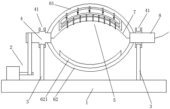
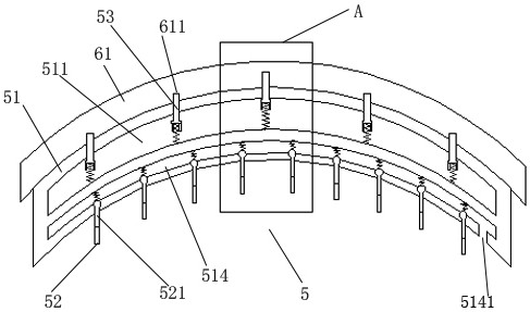
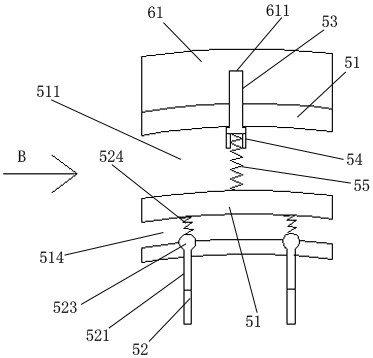
[0026] Such as Figures 1 to 7 As shown, a bow-shaped cable stranding machine includes a base 1, a driving mechanism 2, an incoming wire shaft 4, an outgoing wire shaft 8, an arc-shaped twisting bow, a support rod 3, and a threading assembly 5. The drive mechanism 2 is installed on one side of the upper end of the base 1 . Two parallel supporting rods 3 are installed on the base 1; the incoming wire shaft 4 and the outgoing wire shaft 8 are respectively rotated and installed on the upper ends of the supporting rods 3; the arc-shaped twisting bow includes an upper arc-shaped twisting bow 61 and the lower arc twisting bow 62; the upper and lower arc twisting bows 61 and the lower arc twisting bows 62 are fixed symmetrically up and down between the inlet shaft 4 and the outlet shaft 8; the drive mechanism 2 drives the inlet shaft 4 to rotate, Th...


PUM


Abstract

The invention discloses an arch type cabling stranding machine; the arch type cabling stranding machine comprises a base, a driving mechanism, a wire inlet shaft, a wire outlet shaft, an arc-shaped stranding bow, a supporting rod and a threading assembly; the threading assembly comprises an elastic plate, a wiring ring, a floating block, an abutting-pressing elastic body, a limiting rod, a clamping rod and a limiting elastic body; according to the machine, the sliding and penetrating buckle structure of the wiring ring is realized, so that it is very convenient to detach and mount; the clamping rod glidingly penetrates into an inserting cavity through a penetrating opening, and then the clamping rod and a clamping ball are embedded into a clamping groove below the inserting cavity downwards in the inserting cavity, and then the clamping rod and the clamping ball are firmly pressed and clamped in the clamping groove through the pressing effect of the limiting elastic body, so that the movable connection of the wiring ring is realized, and disassembly and installation of the wiring ring are very convenient.

Description

technical field [0001] The invention relates to a bow type cable stranding machine. Background technique [0002] The stranding machine is a kind of stranding mechanical equipment that can be widely used in various types of soft and hard conductor wires, so that multiple single conductors can be twisted into one strand to meet the technical requirements of the wire. In the existing bow-shaped cable stranding machine, a routing ring or a routing roller is directly installed on the inner side of the arc-shaped twisting bow to guide the cable for transportation. The continuous rotation of the twisted bow tends to make the cable slack on the routing ring or roller, which affects the twisting effect of the cable; in addition, the cable and the routing ring or roller are generally rigidly connected without a buffer mechanism, which makes the cable and the routing Wire rings or rollers are prone to friction and affect the quality of the cable; in addition, the existing routing rin...

Claims


Application Information

Patent Timeline
Patent Type & Authority Patents(China)
IPC IPC(8): H01B13/02
CPCH01B13/0207
Inventor 谭礼春
Owner JIANGSU HONTA MACHINERY
Learn More