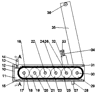
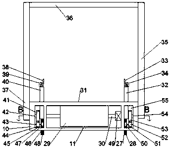
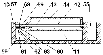
[0020] Combine below Figure 1-4 The present invention will be described in detail, in which, for the convenience of description, the following directions are specified as follows: figure 1 The vertical, horizontal, front, and rear directions of the projection relationship are the same.
[0021] The portable multifunctional treadmill described with reference to FIGS. 1-4 includes a base 10 in which a rotating groove 11 is provided, a front groove 47 is provided in front of the rotating groove 11, and a rear of the rotating groove 11 A rear groove 55 is provided, a left cavity 56 is provided on the left side of the front groove 47, an upper groove 57 is provided above the left cavity 56, a left rotating shaft 17 is rotatably connected in the rotating groove 11, and the left rotating shaft 17 is fixed A left pulley 18 is connected, a motor 49 is fixedly connected to the rear wall of the rotating slot 11, and the motor 49 is power connected with a right rotating shaft 30, and the right rotating shaft 30 is fixedly connected with a right pulley 29, the right pulley 29 A conveyor belt 15 is connected to the left pulley 18 in transmission. The front groove 47 is rotated with a front stretching plate 40 for arm stretching, and the rear groove 55 is rotated with a rear stretching plate for arm stretching. Stretching plate 32, the upper left side of the rotating groove 11 is rotated with a foot fixing frame 14 for sit-up support, the base 10 is respectively rotated forward and backward with a front rotating rod 37 and a rear rotating rod 35, the front groove 47 A front leg 46 and a rear leg 27 for adjusting the inclination are slidably connected to the inner wall of the rear groove 55, and rotating the front rotating rod 37 and the rear rotating rod 35 counterclockwise can move the front stretch plate 40, The rear stretching board 32, the front legs 46, the rear legs 27, and the leg fixing frame 14 are effectively housed.
[0022] Advantageously, a first shaft 20, a second shaft 22, a third shaft 24, and a fourth shaft 26 are rotatably connected between the left shaft 17 and the right shaft 30 in the rotating groove 11, and the first shaft 20. The second shaft 22, the third shaft 24, and the fourth shaft 26 are respectively fixedly connected to the first guide wheel 19, the second guide wheel 21, the third guide wheel 23, and the fourth guide wheel 25. The rotating groove 11 is on the upper left A left baffle 12 is fixedly connected to the side, a right baffle 31 is fixedly connected to the upper right side of the rotating groove 11, and a middle baffle 16 is fixedly connected to the upper part of the rotating groove 11 symmetrically forward and backward.
[0023] Beneficially, the ends of the front rotation rod 37 and the rear rotation rod 35 are fixedly connected with a support rod 36, and the lower end of the front rotation rod 37 is fixedly connected with a front short shaft 42 rotatably connected with the front wall of the front groove 47, The front stub shaft 42 is fixedly connected with a right front gear 41, the rear rotation rod 35 is fixedly connected with a rear stub shaft 54 rotatably connected with the rear wall of the rear groove 55, and the rear stub shaft 54 is fixedly connected with a right rear gear 53.
[0024] Beneficially, a front lower gear 44 is meshed below the right front gear 41, and the front lower gear 44 is fixedly connected with a front lower stub shaft 43 rotatably connected with the inner wall of the front groove 47, and the front lower stub shaft 43 is fixedly connected There is a front sector gear 45, and a front rack 48 intermittently meshing with the front sector gear 45 is fixedly connected to the front leg 46.
[0025] Beneficially, a rear lower gear 52 is engaged below the right rear gear 53, and the rear lower gear 52 is fixedly connected with a rear lower stub shaft 51 rotatably connected to the inner wall of the rear groove 55, and the rear lower stub shaft 51 is fixed. A rear sector gear 50 is connected, and a rear rack 28 intermittently meshing with the rear sector gear 50 is fixedly connected to the rear leg 27.
[0026] Advantageously, the right front gear 41 is meshed with a right middle gear 70, the right middle gear 70 is fixedly connected with a right middle short shaft 71 rotatably connected with the inner wall of the front groove 47, and the right middle gear 70 is meshed with a left middle gear. Gear 68, the left middle gear 68 is fixedly connected with a left middle short shaft 69 rotatably connected with the inner wall of the front groove 47, and the left middle short shaft 69 is fixedly connected with the front stretching plate 40.
[0027] Advantageously, the right rear gear 53 is meshed with a middle rear gear 74, the middle rear gear 74 is fixedly connected with a middle rear short shaft 75 rotatably connected with the inner wall of the rear groove 55, and the middle rear gear 74 meshes with a left The rear gear 72, the left rear gear 72 is fixedly connected with a left rear short shaft 73 rotatably connected with the inner wall of the rear groove 55, and the left rear short shaft 73 is fixedly connected with the rear stretch plate 32.
[0028] Advantageously, a front spring 39 is fixedly connected to the front tension plate 40, a front handle 38 is fixedly connected to the front spring 39, a rear spring 34 is fixedly connected to the rear tension plate 32, and the rear spring A rear handle 33 is fixedly connected to 34.
[0029] Advantageously, the left middle gear 68 is meshed with a left front gear 65, the left front gear 65 is fixedly connected with a left front short shaft 67 rotatably connected with the inner wall of the front groove 47, and the left front short shaft 67 is fixedly connected with a right bevel gear 66. The right bevel gear 66 meshes with a left bevel gear 64, and the left bevel gear 64 is fixedly connected with an outer transverse shaft 63 rotatably connected with the left wall of the front groove 47, and the outer transverse shaft 63 extends to the The left cavity 56 is fixedly connected with a lower bevel gear 62, the lower bevel gear 62 is meshed with an upper bevel gear 61, and the upper bevel gear 61 is fixedly connected with a short vertical shaft 60 rotatably connected with the upper wall of the left cavity 56 , The short vertical shaft 60 extends into the upper groove 57 and is fixedly connected with a lower left bevel gear 59, the lower left bevel gear 59 is meshed with an upper left bevel gear 58, and the upper left bevel gear 58 is fixedly connected with the upper The inner wall of the groove 57 is rotatably connected with a left horizontal shaft 13, and the left horizontal shaft 13 extends into the rotating groove 11 and is fixedly connected with the foot fixing frame 14.
[0030] The fixing and connecting methods described in this embodiment include, but are not limited to, bolting, welding and other methods.
[0031] The sequence of mechanical actions of the entire device:
[0032] 1. During training, start the motor 49 to drive the right rotation shaft 30 to rotate, thereby driving the right pulley 29 to rotate, thereby driving the conveyor belt 15 to move, and the human body can stand on the conveyor belt 15 for running training. Rotating the lever 36 drives the front rotation rod 37 and the rear rotation rod 35 to rotate, thereby driving the front short shaft 42 to rotate, thereby driving the right front gear 41 to rotate, thereby driving the front lower gear 44 Rotating, thereby driving the front lower short shaft 43 to rotate, thereby driving the front sector gear 45 to rotate, thereby driving the rear short shaft 54 to rotate, thereby driving the right rear gear 53 to rotate, thereby driving the rear lower gear 52 rotates, thereby driving the lower rear short shaft 51 to rotate, thereby driving the rear sector gear 50 to rotate. At this time, the front sector gear 45 meshes with the front rack 48, so that the front foot 46 moves up and down, At the same time, the rear sector gear 50 meshes with the rear rack 28 to drive the rear foot 27 to move up and down, thereby adjusting the inclination of the entire device.
[0033] 2. Stop the motor 49, and stretch the front handle 38 and the rear handle 33 to perform arm strength training. The human body lies on the conveyor belt 15, and the feet are inserted into the foot fixing frame 14 to perform Sit-up training.
[0034] 3. After the training, turn the front rotation rod 37 and the rear rotation rod 35 counterclockwise to drive the front foot 46 and the rear foot 27 into the front groove 47 and the rear groove 55, respectively At the same time, the front stretch plate 40 and the rear stretch plate 32 rotate to enter the front groove 47 and the rear groove 55 respectively, while the foot fixing frame 14 rotates to enter the rotation groove 11, so The front rotating rod 37 and the rear rotating rod 35 are parallel to the base 10 after rotating, so that the entire device is effectively stored together.
[0035] The above-mentioned embodiments are only to illustrate the technical concept and features of the present invention, and their purpose is to enable those skilled in the art to understand and implement the content of the present invention, and they cannot limit the protection scope of the present invention. All equivalent changes or modifications made according to the spirit of the present invention should be covered by the protection scope of the present invention.