
Device for monitoring plant growing environment

A technology for environmental monitoring and plant growth, applied in the field of devices for monitoring plant growth environment, can solve the problems of unstable connection, dumping damage, environmental monitoring device dumping damage, etc., and achieves the effect of facilitating stable storage, avoiding dumping damage, and stable connection

Inactive Publication Date: 2019-11-08
汤小梅
View PDF0 Cites 6 Cited by
  • Summary
  • Abstract
  • Description
  • Claims
  • Application Information

AI Technical Summary

Problems solved by technology

[0003] In order to overcome the deficiencies of the existing technologies, a plant growth environment monitoring device is proposed to solve the problem of unstable connection between the environmental monitoring device and the ground, and the problem that the environmental monitoring device is easily tilted and the environmental monitoring device is dumped and damaged, so as to achieve a stable connection between the environmental monitoring device and the ground and avoid environmental damage. Beneficial Effects of Monitoring Device Falling Damage

Method used


Image

  • Device for monitoring plant growing environment
  • Device for monitoring plant growing environment
  • Device for monitoring plant growing environment

Examples


Embodiment Construction

[0022] The technical solutions of the present invention will be further described below in conjunction with the accompanying drawings and through specific implementation methods.

[0023] Wherein, the accompanying drawings are only for illustrative purposes, showing only schematic diagrams, rather than physical drawings, and should not be construed as limitations on this patent; in order to better illustrate the embodiments of the present invention, some parts of the accompanying drawings will be omitted, Enlargement or reduction does not represent the size of the actual product; for those skilled in the art, it is understandable that certain known structures and their descriptions in the drawings may be omitted.

[0024] In the drawings of the embodiments of the present invention, the same or similar symbols correspond to the same or similar components; , "inner", "outer" and other indicated orientations or positional relationships are based on the orientations or positional ...


PUM


Abstract

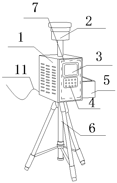
The invention discloses a device for monitoring plant growing environment. A structure of the device comprises a support device. The problem that the equipment is easy to topple over and damage sincethe environment monitoring device is in unstable connection with the ground and easy to topple over is solved. A support device is arranged at the bottom of an environment monitoring instrument; the support rod is connected with the environment monitoring instrument through a fixed disk, and a mounting slot in the fixed disk is aligned with the fixed slot at the bottom of the environment monitoring instrument and then is inserted into the same to fix through a bolt, and then each fixed rod is orderly connected with a connector through each first rotating shaft, a fulcrum is connected with a sliding ring through a second rotating shaft, and the left side of the fulcrum bar is connected with a buffer cushion, the sliding ring is pulled to slide down to an appropriate distance, so that the fulcrum bar and the sliding ring are in horizontal state; the fulcrum bar pulls the buffer cushion pad, the buffer cushion pad drives an expansion link to extend through the fixed rod, thereby enablingan auxiliary frame to be unfolded in a triangle to contact with the ground to relieve the downward pressure of the equipment through a buffer cushion, the equipment can be stably stored, the environment monitoring device can stably connect with the ground, thereby preventing the environment monitoring device from toppling over and damaging.

Description

technical field [0001] The invention relates to the technical field of environmental monitoring, in particular to a plant growth environment monitoring device. Background technique [0002] With the continuous progress of the society, the traditional agricultural production mode can no longer meet the needs of the development of modern civilization. The new type of facility agriculture is sought after by people in the industry. The so-called agricultural equipment is actually not limited by time and space. It can be used on plateaus, deep mountains, Agricultural production is carried out in special environments such as deserts, and the environmental conditions directly affect the growth of crops. The corresponding environmental monitoring devices can effectively monitor the temperature and humidity around the planting site, which is convenient for users to know in time. However, the structure of environmental monitoring devices currently on the market It is complicated and h...

Claims


Application Information

Patent Timeline
Patent Type & Authority Applications(China)
IPC IPC(8): G01D21/02G01D11/30F16M11/32G08C17/02
CPCF16M11/32F16M2200/08G01D11/30G01D21/02G08C17/02
Inventor 汤小梅
Owner 汤小梅
Learn More