Fabricated power box foundation machining mold and manufacturing method

A processing mold and assembly technology, which is applied in the field of basic processing molds and manufacturing of assembled power boxes, can solve the problems of heavy weight, product offset, and difficult to move, and achieve the effect of saving resources and increasing the folding rate

Active Publication Date: 2022-03-01
江西泽皓电气科技有限公司 +1
View PDF6 Cites 0 Cited by
  • Summary
  • Abstract
  • Description
  • Claims
  • Application Information

AI Technical Summary

Problems solved by technology

[0005] The object of the present invention is to provide a basic processing mold for an assembled power box and a manufacturing method to solve the problem that the existing basic processing mold for an assembled electric box proposed in the above background technology usually needs to be produced at the bottom first. Afterwards, the upper part is produced, but since the upper part is in a semi-closed state, it is not easy to center the upper mold, which may cause deviation of the product from pouring bleeding, resulting in different wall thickness of the product, resulting in poor product quality The problem arises; secondly, because the upper mold itself adopts a rigid mold design, the mold itself is heavy and in a semi-closed state, large-scale equipment is not easy to operate inside, and can only be pushed from the outside, so it is difficult to move, and may cause the upper mold to appear. The problem of overturning appeared; secondly, the use of small internal equipment made it difficult to take out the equipment in the later stage without dismantling the formwork, thus affecting the continuous use of the equipment

Method used


Image

  • Fabricated power box foundation machining mold and manufacturing method
  • Fabricated power box foundation machining mold and manufacturing method
  • Fabricated power box foundation machining mold and manufacturing method

Examples


Embodiment Construction

[0030] The following will clearly and completely describe the technical solutions in the embodiments of the present invention with reference to the accompanying drawings in the embodiments of the present invention. Obviously, the described embodiments are only some, not all, embodiments of the present invention. Based on the embodiments of the present invention, all other embodiments obtained by persons of ordinary skill in the art without creative efforts fall within the protection scope of the present invention.

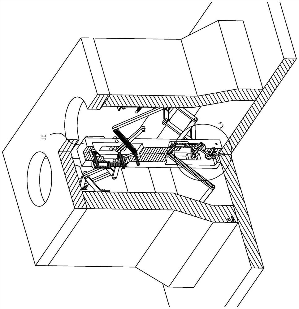
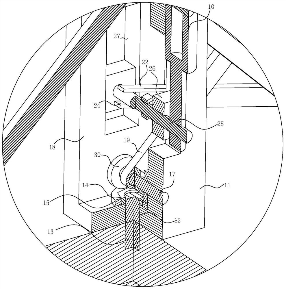
[0031] see Figure 1-8 , the present invention provides a technical solution: an assembled power box foundation processing mold, including four hydraulic rods 10 divided into two groups, including a column 11, and the lower end of the column 11 is provided with a fixing hole 12 for fixing, and the fixing hole 12 There is a screw 13 inside, and the lower end of the screw 13 is fixed on the central bottom plate of the mold. The upper end of the screw 13 passes throug...


PUM


Abstract

The invention discloses an assembly type power box foundation processing mold in the technical field of assembly type power boxes, which comprises four hydraulic rods divided into two groups and a stand column, a fixing hole for fixing is formed in the lower end of the stand column, a screw rod is arranged in the fixing hole, and the lower end of the screw rod is fixedly arranged on a mold central bottom plate. The outer side of the locking bolt is in contact connection with a one-way wheel, the one-way wheel is rotationally arranged on the stand column, and centering devices are arranged on the periphery of the side wall of the upper end of the stand column; the problems that during production of an assembly type power box foundation machining mold, bottom production is generally needed firstly, then upper production is needed, an upper mold is not prone to being centered due to the fact that the upper half portion is in a semi-closed state, a product which is subjected to pouring bleeding may deviate, and the production efficiency is high are solved. And therefore, the product quality is poor due to different wall thicknesses of products.

Description

technical field [0001] The invention relates to the technical field of an assembled electric box, in particular to a base processing mold and a manufacturing method for an assembled electric box. Background technique [0002] Prefabricated buildings are buildings assembled with prefabricated components. They are based on the entire production process of construction projects driven by industrialized production. Compared with traditional buildings, the assembly process of prefabricated components of prefabricated buildings is simple, the construction period is short, and the prefabricated components are unified, which is convenient for on-site management and storage. Therefore, prefabricated buildings can shorten the construction period by 25%-30%, and save about 50% of water. %, save wood by 80%, reduce construction waste by 70%, and greatly reduce dust and noise pollution; most of the existing underground power boxes are processed by assembly-type processing molds, but due ...

Claims


Application Information

Patent Timeline
Patent Type & Authority Applications(China)
IPC IPC(8): B28B23/02E02D27/44
CPCB28B23/022E02D27/44
Inventor 彭洁刘清华卢伟平杜炳霞易绍新周海玉彭可
Owner 江西泽皓电气科技有限公司
Why Eureka
Try Eureka