Stamping Process of Seat Seat Plate and Its Special Stamping Die

A stamping die and seat plate technology, which is applied in the field of automotive stamping parts, can solve problems such as product formation defects, and achieve the effect of improving stamping pass rate and high stamping efficiency

Active Publication Date: 2020-09-01
武汉市尚佳盛汽车配件有限公司
View PDF4 Cites 0 Cited by
  • Summary
  • Abstract
  • Description
  • Claims
  • Application Information

AI Technical Summary

Problems solved by technology

But this method is easy to form folds at the intersection of the first side part 121 and the second side part 122, and the product will form defects.

Method used


Image

  • Stamping Process of Seat Seat Plate and Its Special Stamping Die
  • Stamping Process of Seat Seat Plate and Its Special Stamping Die
  • Stamping Process of Seat Seat Plate and Its Special Stamping Die

Examples


Embodiment 1

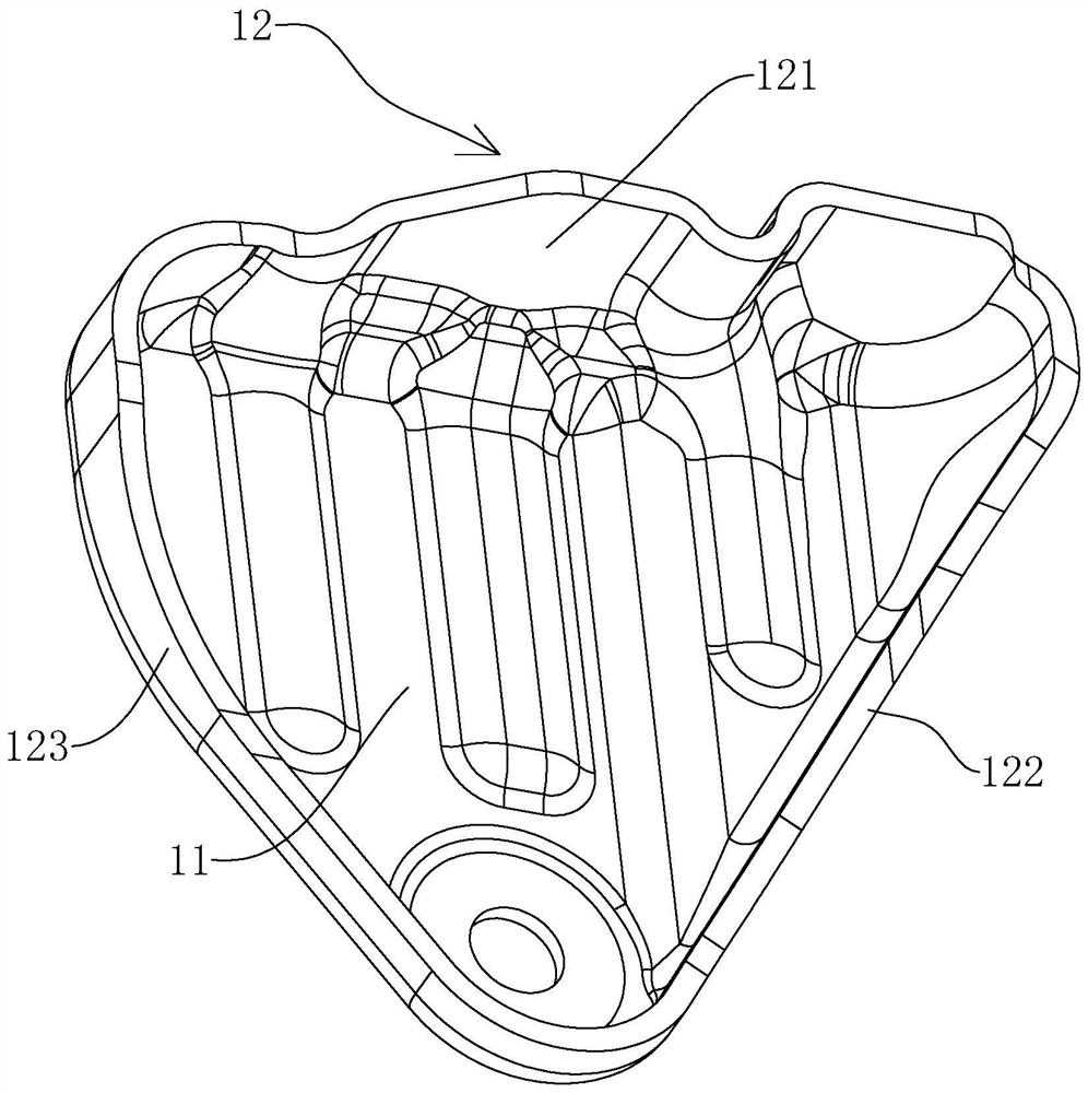
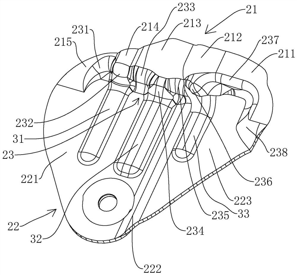
[0027] Embodiment 1: A stamping process for a seat seat plate, such as figure 2 , the flat steel plate 8 to be stamped is stamped once to form the upper planar portion 21 , the lower planar portion 22 , and the tensile transition portion 23 .

[0028] The upper plane portion 21 is higher than the lower plane portion 22, and the upper plane portion 21 includes an upper plane one 211, a first slope 212, an upper plane two 213, an arched surface 214, a second slope 215, and an upper plane one 211 connected in sequence. 213 higher than the upper plane. The first slope surface 212 is obliquely arranged, one end of the first slope surface 212 is connected with the upper plane one 211, the other end is connected with the upper plane two 213, the middle of the arched surface 214 is arched, and the two ends of the arched surface 214 are connected with the upper plane two respectively. 213 is connected with the second slope 215 , and the second slope 215 arcs downward from the end con...

Embodiment 2

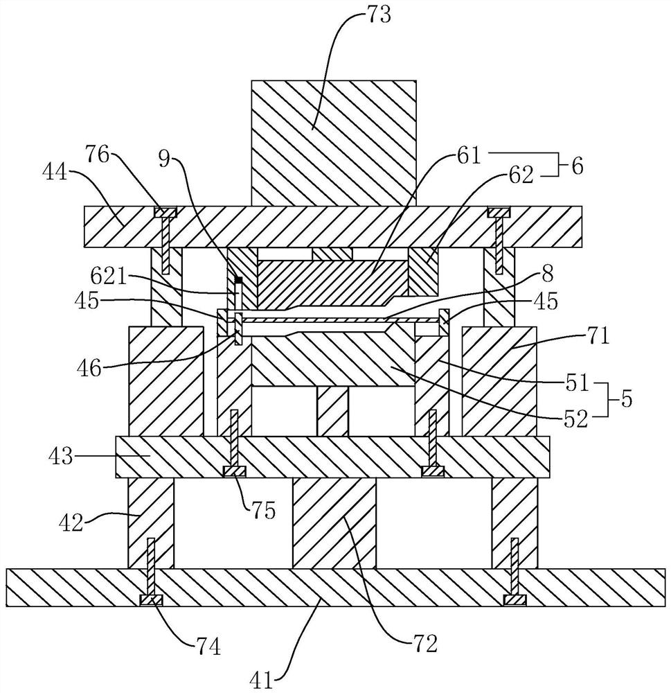
[0040] Embodiment 2: the stamping die that is installed in the stamping process of the seat seat plate, such as image 3 , comprising a support 41, a column 42 fixed above the support 41, a bottom plate 43 fixed on the column 42, a lower mold 5 fixed above the bottom plate 43, a first hydraulic cylinder 71 fixed above the bottom plate 43, and a first The mounting plate 44 on which the piston rod of the hydraulic cylinder 71 is fixed, the upper die 6 fixed on the mounting plate 44 and positioned above the lower die 5 .

[0041] The columns 42 are arranged in two rows, and the second hydraulic cylinder 72 is arranged in the middle of the columns 42 of the two rows. The support 41 and the column 42 are fixed by the first bolt 74 , the first bolt 74 is a counterbore bolt, and the first bolt 74 passes through the support 41 and extends into the column 42 to be threadedly connected with the column 42 . The first hydraulic cylinder 71 is arranged in two rows, and the lower mold 5 is l...


PUM


Abstract

The invention discloses a seat plate stamping technology and a special stamping die thereof. According to the seat plate stamping technology, a flat and straight to-be-stamped steel plate is subjectedto primary stamping so as to form an upper plane part, a lower plane part and a stretching transition part. The upper plane part comprises a first upper plane, a first slope surface, a second upper plane, a hunching surface and a second slope surface which are connected in sequence. The lower plane part comprises a first lower plane, a transition arc-shaped surface and a second lower plane whichare connected in sequence, and the second lower plane is higher than the first lower plane. The lower plane part is hunched up to form a first convex rib, a second convex rib and a third convex rib. The first convex rib and the second convex rib are located on the first lower plane, and the third convex rib is located on the second lower plane. The stretching transition part comprises a first arc-shaped transition surface, a first convex surface, a first concave surface, a second convex surface, a second concave surface, a third convex surface, a U-shaped surface and a second arc-shaped transition surface which are connected in sequence. Then, secondary stamping is conducted and a final product is formed. According to the scheme, the wrinkling phenomenon cannot happen to the product easilyin the twice stamping mode.

Description

technical field [0001] The invention relates to the field of automobile stamping parts, in particular to a stamping process for a seat seat plate and a special stamping die thereof. Background technique [0002] Stamping is a forming processing method that applies external force to plates, strips, pipes and profiles by presses and molds to cause plastic deformation or separation to obtain workpieces (stamping parts) of required shape and size. [0003] Due to the high speed of stamping and forming, many auto parts are currently formed by stamping. [0004] The car seat board is a part used on the car seat. Generally, the seat is composed of multiple seat boards. The specific product structure is as follows: figure 1 As shown, it includes a bottom surface 11 and a side surface 12 surrounding the bottom plate 43. The side surface 12 is mainly formed by sequentially connecting the first side portion 121, the second side portion 122 and the third side portion 123. The bottom pl...

Claims


Application Information

Patent Timeline
Patent Type & Authority Patents(China)
IPC IPC(8): B21D22/02B21D37/10
CPCB21D22/02B21D37/10
Inventor 李军何丽平余扬帆刘洪新文佳思刘水荣
Owner 武汉市尚佳盛汽车配件有限公司
Why Eureka
Try Eureka