A non-contact micro-vibration visual measurement method

A micro-vibration and visual measurement technology, applied in the field of computer vision, can solve problems such as measurement and analysis of micro-vibration signals

Active Publication Date: 2021-05-14
HEFEI UNIV OF TECH
View PDF8 Cites 0 Cited by
  • Summary
  • Abstract
  • Description
  • Claims
  • Application Information

AI Technical Summary

Problems solved by technology

However, these methods generally require humans to determine the frequency parameters of the band-pass filter based on prior knowledge, and have not effectively measured and analyzed tiny vibration signals.

Method used


Image

  • A non-contact micro-vibration visual measurement method
  • A non-contact micro-vibration visual measurement method
  • A non-contact micro-vibration visual measurement method

Examples


Embodiment Construction

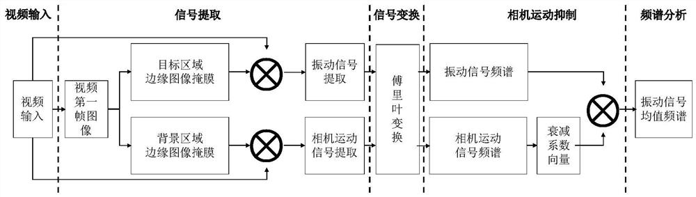
[0030] combine figure 1 , the non-contact micro-vibration visual measurement technology of the present invention comprises the following steps:

[0031] Step S1: collect video data of vibrating objects in nature to extract tiny vibration signals;

[0032] In this step, according to an embodiment of the present invention, specifically:

[0033] 1a) A Canon camera EOS 600D is used to capture a video of a vibrating object in a natural environment. The frame rate of the camera is 50 frames per second, the image resolution is 1280×720, the video acquisition time is 7 seconds, and it is saved in avi video format. Using color space conversion, it is converted from RGB space to YIQ space, and the video sequence of Y (brightness) channel is extracted for subsequent analysis.

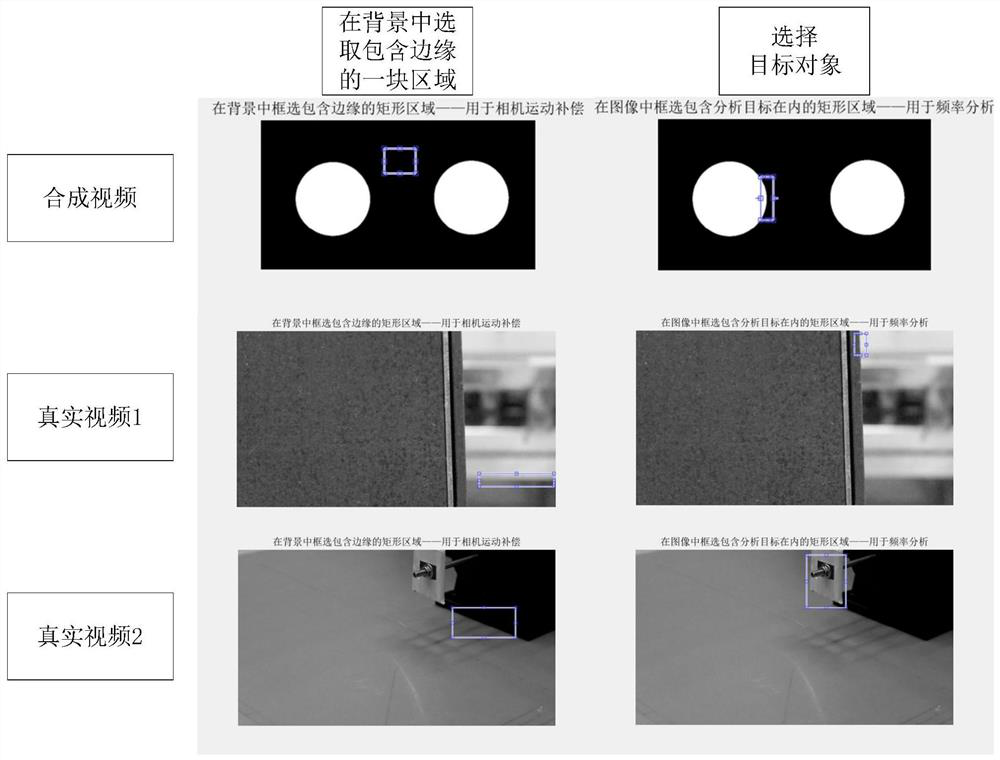
[0034] 1b) Extract the first frame image in the video sequence, and manually select the vibration target region (ROI); use the canny operator to detect its edge, and then generate an edge mask Image Mask with ...


PUM


Abstract

The invention discloses a non-contact micro vibration visual measurement method. This method aims to study and analyze the frequency characteristics of micro-vibration signals. This technology mainly includes micro-vibration signal extraction, camera motion interference suppression processing, and signal analysis. The steps of the method are as follows, step S1: collect video data of vibrating objects in nature to extract tiny vibration signals; step S2: use Fourier transform to transform the tiny vibration signals into frequency domain, and obtain their frequency spectrum; step S3: obtain the frequency spectrum from the Extract the camera motion signal from the video data, analyze and process the camera motion signal to obtain the attenuation coefficient vector Coe; Step S4: multiply the attenuation coefficient vector Coe and the frequency spectrum of each micro vibration signal, and obtain the average value Vibration target spectrum.

Description

technical field [0001] The invention belongs to the technical field of computer vision, and relates to a non-contact micro-vibration visual measurement method in a real scene. Background technique [0002] The vibration characteristics of a vibrating object are closely related to its own state. For example, the vibration information generated during the operation of an industrial system reflects its structural characteristics and operating status. Bad vibration not only affects the performance of the system, but even has serious safety consequences. [0003] The existing vibration measurement methods are divided into two types: contact and non-contact. Contact vibration measurement sensors, such as piezoelectric sensors, acceleration sensors, etc., are generally installed on the surface of the object to be measured, and the vibration measurement is realized by converting the vibration signal into an electrical signal. During the measurement process, the mechanical loss of...

Claims


Application Information

Patent Timeline
Patent Type & Authority Patents(China)
IPC IPC(8): G01H9/00
CPCG01H9/00
Inventor 杨学志张龙黄飞龙张礼俊辛宜曈张肖
Owner HEFEI UNIV OF TECH
Why Eureka
Try Eureka