Electric brake system for a vehicle

A technology for electric braking and vehicles, applied in braking control systems, road vehicle drive control systems, brakes, etc., can solve problems such as abnormal relay units, achieve easy monitoring, reduce hysteresis, and improve charging characteristics

Active Publication Date: 2019-11-15
HALDEX VIE (SHANGHAI) ELECTROMECHANICAL BRAKE SYST CO LTD
View PDF13 Cites 2 Cited by
  • Summary
  • Abstract
  • Description
  • Claims
  • Application Information

AI Technical Summary

Problems solved by technology

[0004] US 2004 / 0212250 A1 describes that there are also problems in redundant electric braking systems, which can arise when anomalies occur in the relay unit used to switch between the power supply from the main battery and the auxiliary battery

Method used


Image

  • Electric brake system for a vehicle
  • Electric brake system for a vehicle
  • Electric brake system for a vehicle

Examples


Embodiment Construction

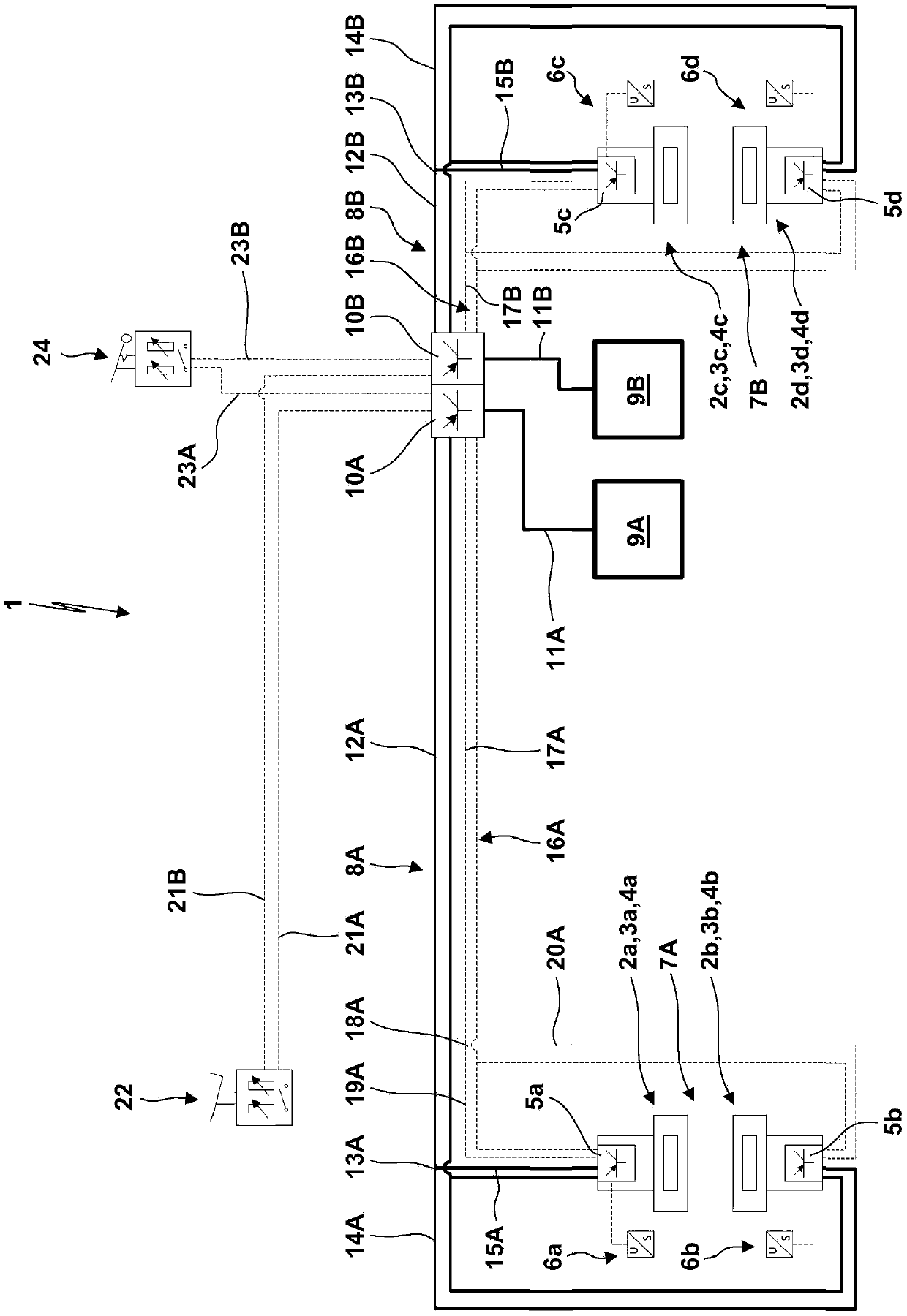
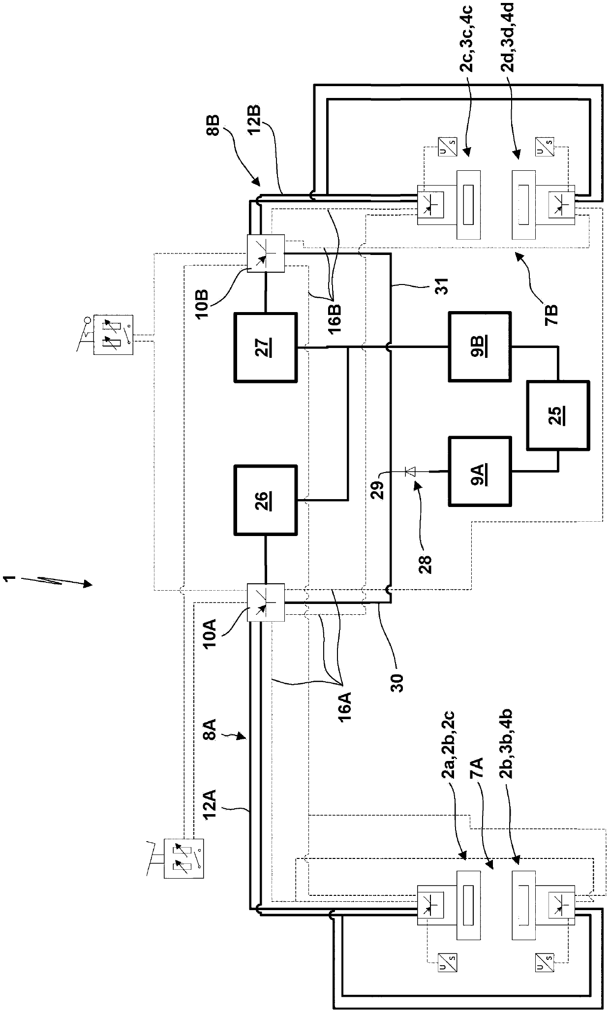
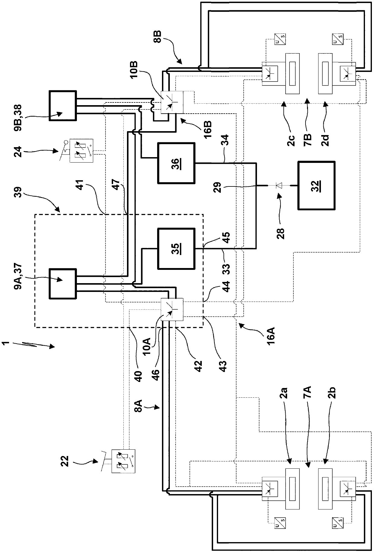
[0093] In the figures, the same reference numerals are used for components having the same or equivalent function and / or design. If the same parts are used several times in an embodiment, these parts are marked with the same reference numerals and an additional distinguishing letter a, b, c, . . . or A, B. The use of a reference number in the following description without distinguishing letters a, b, c, ... or A, B may refer to all parts with this reference number, or to only a single part or any number of these parts. If the same component or component group is used multiple times for an embodiment, only one of these components or component groups will be described in some cases. In this case, however, the other components or groups of components apply correspondingly.

[0094] figure 1 An electric braking system 1 is shown. The electric braking system 1 comprises four braking devices 2a-2d. The brake devices 2a-2d respectively comprise brake actuators 3a-3d respectively...


PUM


Abstract

The invention relates to an electric brake system (1) for a vehicle. The electric brake system (1) comprises electric brake devices (2). The electric brake devices (2) are powered and controlled by redundant capacitor-based power sources (9A, 9B) and redundant control circuits (16A, 16B). The capacitor-based power source (9A, 9B) can be integrated into axle modules (39A, 39B) located close to a vehicle axle (61A, 61B). The capacitor-based power sources (9A, 9B) are recharged by a hub generator, a regeneration power source (32).

Description

technical field [0001] The invention relates to an electric braking system for a vehicle, by way of example only, in particular a commercial vehicle, a vehicle propelled exclusively by electric energy and / or a hybrid vehicle propelled by electric energy and an internal combustion engine. The vehicle may be a bus, commercial vehicle, tractor, train and / or trailer. In this type of vehicle, in the electric braking system, the braking force is generated by at least one electric braking device. In an electric brake device, the contact force between brake elements, especially brake pads and brake discs, is controlled by an electric brake actuator. Background technique [0002] EP 1 302 371 A2 describes a known power supply system according to DE 197 55 050.9. In this power supply system, electro-motoric braking devices are powered by two redundant power supplies through a common power supply line. A redundant power supply ensures that the brakes can also be operated in the even...

Claims


Application Information

Patent Timeline
Patent Type & Authority Applications(China)
IPC IPC(8): B60T8/88B60T13/74
CPCB60T8/885B60T2270/413B60T2270/414B60T13/66B60T13/741H02J7/14Y02T10/70B60T13/74B60T7/042B60W10/192B60W20/14B60W30/18127B60W2300/10B60W2300/152B60W2300/14B60Y2200/143B60Y2200/221B60Y2200/30B60Y2200/147B60Y2300/18125B60Y2400/81B60Y2200/92B60T2270/608
Inventor A·尼尔松A·林德奎斯特P·尼尔松
Owner HALDEX VIE (SHANGHAI) ELECTROMECHANICAL BRAKE SYST CO LTD
Why Eureka
Try Eureka