Thermal printer

A technology of thermal printers and print heads, applied in printing devices, printing, etc., can solve problems such as waste, and achieve the effect of simple and practical structure, convenient and quick operation

Pending Publication Date: 2019-11-22
宁波精芯科技有限公司
View PDF4 Cites 3 Cited by
  • Summary
  • Abstract
  • Description
  • Claims
  • Application Information

AI Technical Summary

Problems solved by technology

[0004] At present, the common thermal printers can only meet the printing needs of a certain width of paper. If the width of the printing paper changes, it is necessary to purchase other types of thermal printers. There is a certain waste and needs to be improved.

Method used


Image

  • Thermal printer
  • Thermal printer
  • Thermal printer

Examples


Embodiment Construction

[0040] The present invention will be further described in detail below in conjunction with the accompanying drawings and embodiments.

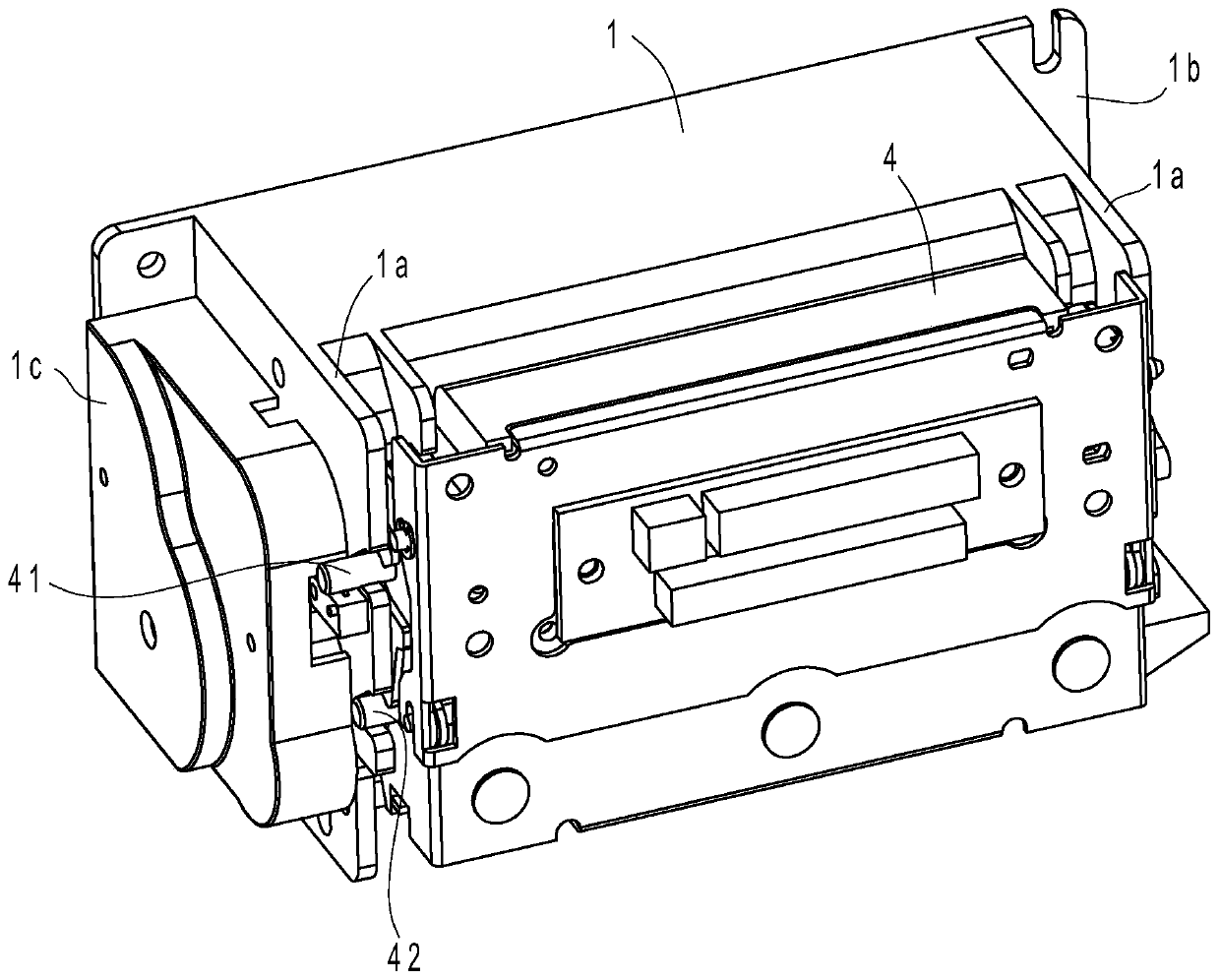
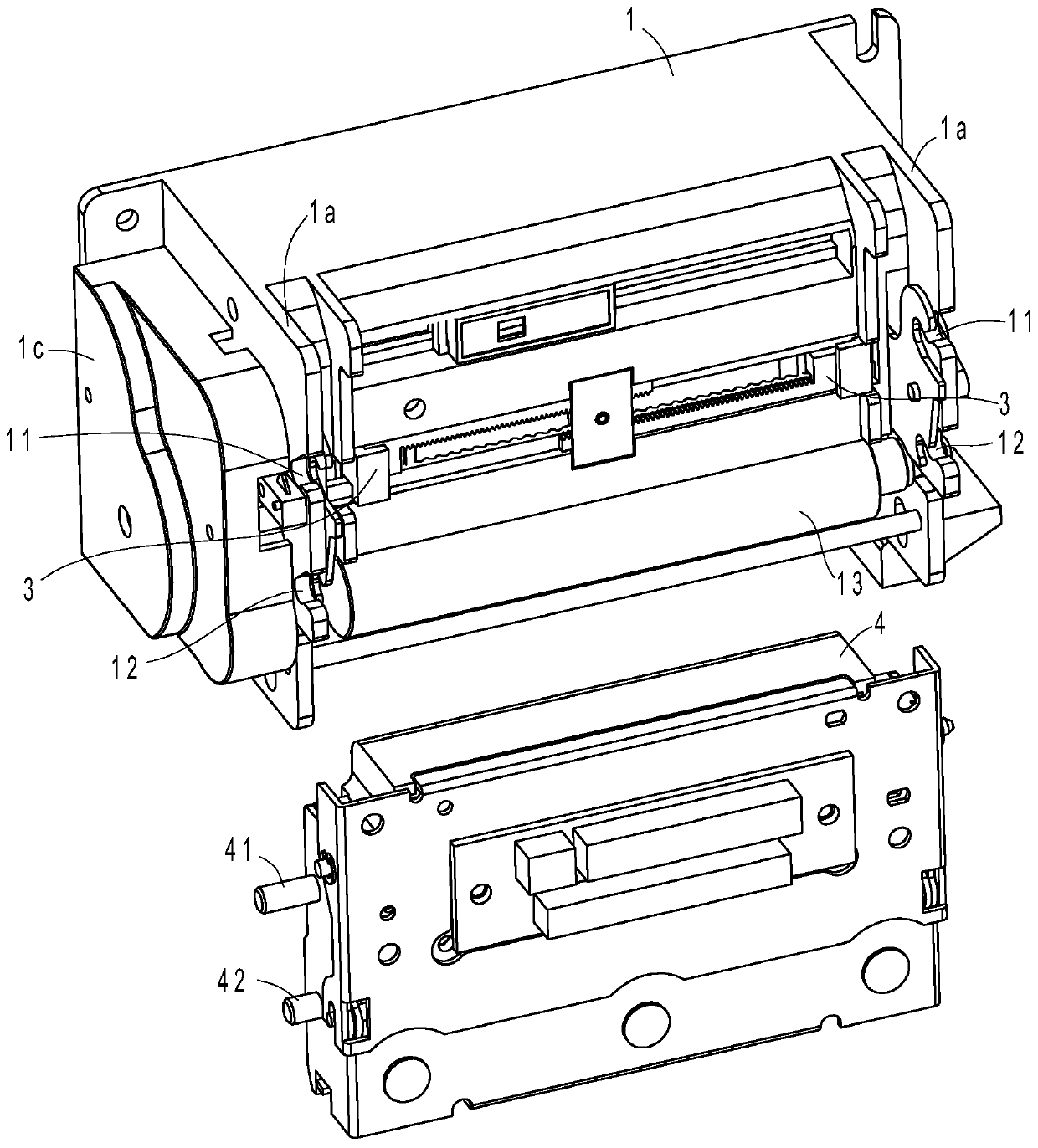
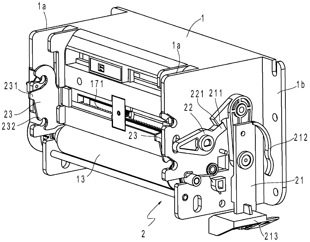
[0041] Such as figure 1 , figure 2 and image 3 As shown, the thermal printer in this embodiment includes a frame 1 , a motor 16 , a transmission gear set 14 , a rubber roller 13 , a frame 4 , a print head assembly 43 , a sliding mechanism 3 and a release mechanism 2 .

[0042] The front end surface of the machine base 1 has a first positioning groove 11 and a second positioning groove 12 respectively; On the connecting portion 1a; the machine base 1 has a retaining wall 1b extending laterally outward. The motor 16 is located on the machine base 1 .

[0043] The transmission gear set 14 is arranged on the machine base 1 and connected with the power output end of the motor 16 , and the gear cover 1c is arranged on the machine base 1 and covers the transmission gear set 14 .

[0044] The rubber roller 13 is rotatably arranged on the machin...


PUM


Abstract

A thermal printer comprises a printer base, a motor, a transmission gear set, a printer assembly, a rack and a rubber roller. The thermal printer is characterized in that a sliding groove is transversely formed in the front end of the printer base; and a sliding mechanism capable of adjusting the paper width is arranged at the front end of the printer base. The width of paper to be printed can beadjusted by adjusting the sliding mechanism, and thus the printer is capable of printing paper of different types, thereby being multifunctional. The thermal printer is convenient and fast to operateand simple and practical in structure.

Description

technical field [0001] The invention relates to a heat-sensitive printer, which is applied to the ticket printing of cash machines and supermarket cash registers. Background technique [0002] Most of the bank's ATMs and supermarket cash registers are equipped with thermal printers for printing transaction receipts or receipts. Thermal printers usually have a casing, and a movement is installed in the casing. The movement is composed of a print head assembly, a frame and a paper cutter, wherein the print head assembly is installed above the frame, and the paper cutter Installed on one side of the frame and print head assembly. A paper-feeding path is formed between the print head assembly and the base, and the thermal printing paper passes through the paper-feeding path. [0003] A rubber roller is installed on the upper end of the machine base of the thermal printer core, and a motor is arranged in the machine base, and the motor drives the rubber roller to rotate through...

Claims


Application Information

Patent Timeline
Patent Type & Authority Applications(China)
IPC IPC(8): B41J11/00B41J2/32
CPCB41J2/32B41J11/0025
Inventor 王建立张敏林枫
Owner 宁波精芯科技有限公司
Why Eureka
Try Eureka