Pay-off device for cable production

A pay-off device and cable technology, applied in conductor/cable supply device, cable/conductor manufacturing, circuit, etc., can solve problems such as inconvenient use, slow replacement speed, and reduced cable production efficiency, and achieve convenient use, fast speed, The effect of improving stability

Inactive Publication Date: 2019-11-26
KINGSIGNAL OPTICAL FIBER & CABLE GANZHOU CO LTD
View PDF0 Cites 3 Cited by
  • Summary
  • Abstract
  • Description
  • Claims
  • Application Information

AI Technical Summary

Problems solved by technology

[0003] The purpose of the present invention is to provide a kind of pay-off device for cable production, which has the advantages of changing the installation structure, changing the pay-off ring quickly, improving the production efficiency of the cable, and being easy to use, which solves the problem that the current pay-off device is difficult to replace. When paying off the wire ring, due to the installation structure, the replacement speed is slow, which reduces the production efficiency of the cable and is inconvenient to use

Method used


Image

  • Pay-off device for cable production
  • Pay-off device for cable production
  • Pay-off device for cable production

Examples


Embodiment Construction

[0016] The following will clearly and completely describe the technical solutions in the embodiments of the present invention with reference to the accompanying drawings in the embodiments of the present invention. Obviously, the described embodiments are only some, not all, embodiments of the present invention. Based on the embodiments of the present invention, all other embodiments obtained by persons of ordinary skill in the art without making creative efforts belong to the protection scope of the present invention.

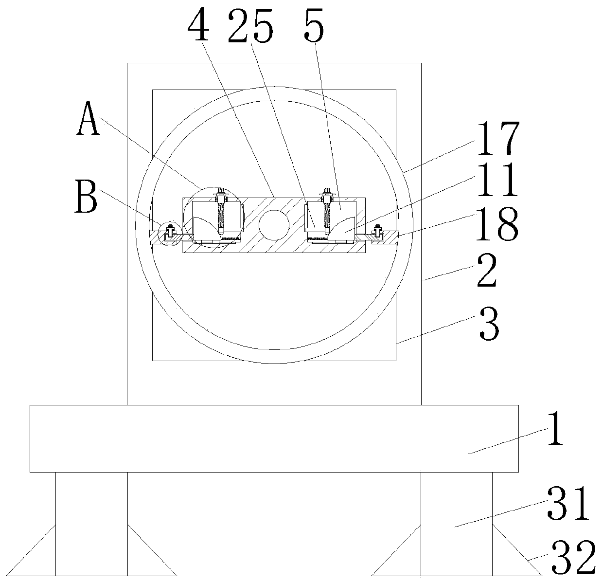
[0017] see Figure 1-3 A pay-off device for cable production, comprising a support plate 1, support legs 31 are fixedly connected to both sides of the bottom of the support plate 1, and triangular stabilizing plates 32 are fixedly connected to the bottoms of both sides of the support leg 31, by setting the support legs 31 and triangular stabilizing plate 32 can improve the stability of the device, the top of the support plate 1 is fixedly connected with the mo...


PUM


Abstract

The invention discloses a pay-off device for cable production. The pay-off device comprises a supporting plate; the top of the supporting plate is fixedly connected with a mounting plate; a motor is fixedly installed on the front surface of the mounting plate; an output end of the motor is fixedly connected with a connecting block; accommodating grooves are formed at the two sides of the interiorof the connecting block; bearings are arranged on the two sides of the top of the connecting block in a penetrating mode; the bottoms of the bearings extend to the interiors of the accommodating grooves; threaded sleeves are fixedly connected to the internal surfaces of the bearings; threaded rods are in threaded connection with the interiors of the threaded sleeves; and tops of the threaded rodspenetrate through the threaded sleeves and extend to the outsides of the threaded sleeves. According to the pay-off device for the cable production provided by the invention, the bearings, the threaded sleeves, the threaded rods, a mounting block, a lug, a movable block, a sliding block, a sliding chute I, a spring I, a clamping rod, a clamping block, a clamping groove, a limiting rod, a spring IIand a limiting groove are matched, so that an existing mounting structure is changed, the speed of replacing a pay-off ring is high, the production efficiency of cables is improved, and the use is convenient.

Description

technical field [0001] The invention relates to the technical field of cable production, in particular to a pay-off device for cable production. Background technique [0002] A cable is usually composed of several wires or groups of wires. The cable is usually composed of a core for transmitting power or electrical signals and a sheath for protection and insulation. A cable with only one core and a smaller diameter is usually called Most of the cable cores in electric wires and cables are made of copper or aluminum. Copper or aluminum is generally wound on the coil. During processing, a pay-off device is required to pay off the wire. However, the current pay-off device is replacing the pay-off. When ringing, due to the installation structure, the replacement speed is slow, which reduces the production efficiency of the cable and is inconvenient to use. Contents of the invention [0003] The purpose of the present invention is to provide a kind of pay-off device for cable ...

Claims


Application Information

Patent Timeline
Patent Type & Authority Applications(China)
IPC IPC(8): H01B13/00
CPCH01B13/0003H01B13/0036
Inventor 李扬朱宇杭孙明杨国勇
Owner KINGSIGNAL OPTICAL FIBER & CABLE GANZHOU CO LTD
Why Eureka
Try Eureka