

Robot mopping control method, master control chip and mopping robot
A technology of a mopping robot and a control method, applied in the field of intelligent robots, can solve problems such as the inability to meet the diverse needs of users for robot mopping.
- Summary
- Abstract
- Description
- Claims
- Application Information
AI Technical Summary
Problems solved by technology
Method used
Image

Examples
Embodiment Construction
[0019] The technical solutions in the embodiments of the present invention will be described in detail below with reference to the drawings in the embodiments of the present invention. It should be understood that the specific embodiments described below are only used to explain the present invention, not to limit the present invention. In the following description, specific details are given to provide a thorough understanding of the embodiments. However, one of ordinary skill in the art would understand that the embodiments may be practiced without these specific details. For example, circuits may be shown in block diagrams in order not to obscure the embodiments in unnecessary detail. In other instances, well-known circuits, structures and techniques have not been shown in detail in order not to obscure the embodiments.
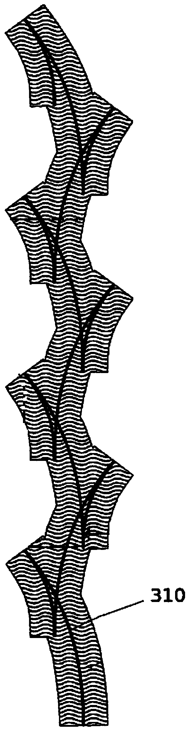
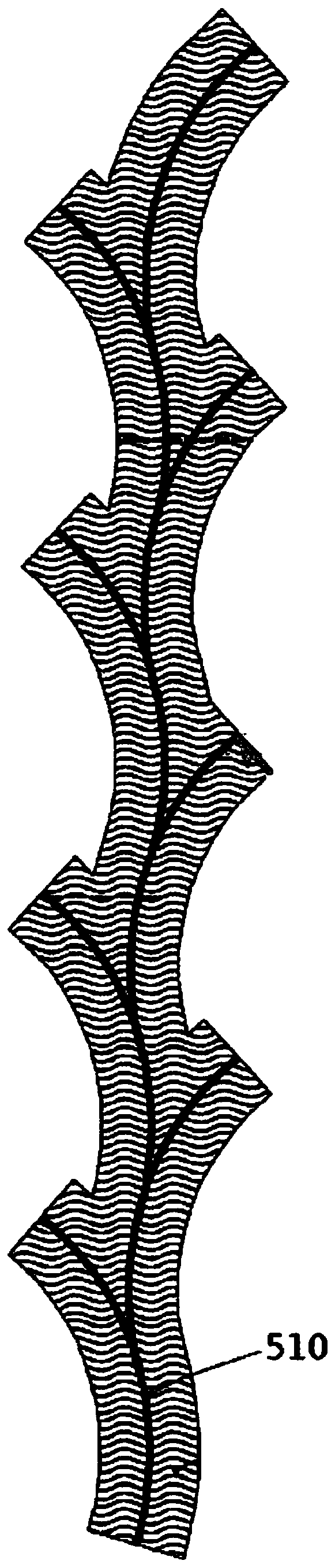
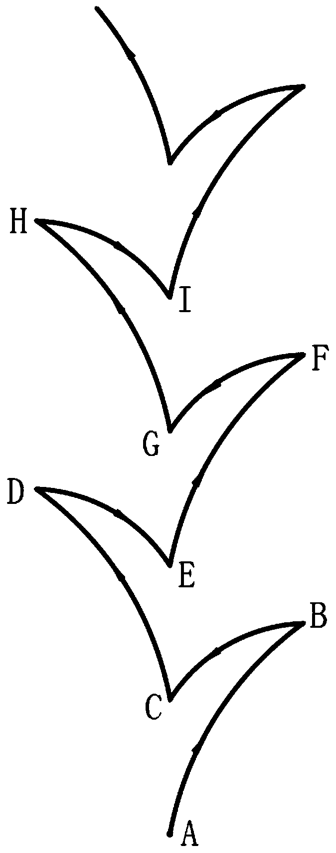
[0020] A control method for mopping the floor by a robot, the robot is a cleaning robot with the function of mopping the floor, which may be a household...
PUM
 Abstract
Description
Claims
Application Information