
A bending machine with gear synchronous drive mechanism

A synchronous drive and bending machine technology, applied in the field of bending machines, can solve the problems of asynchronous drive, component wear, and difficulty for operators, and achieve the effects of avoiding swing, prolonging service life, and reducing maintenance costs.

Active Publication Date: 2021-07-23
马鞍山茂丰重工机械制造有限公司
View PDF14 Cites 0 Cited by
  • Summary
  • Abstract
  • Description
  • Claims
  • Application Information

AI Technical Summary

Problems solved by technology

[0002] When the bending machine is working, the upper mold is driven out of sync and swings. It is difficult for the operator to find out in time when the swing is slight. When the swing amplitude becomes larger, the wear of some parts is more serious.

Method used


Image

  • A bending machine with gear synchronous drive mechanism
  • A bending machine with gear synchronous drive mechanism
  • A bending machine with gear synchronous drive mechanism

Examples


Embodiment Construction

[0017] In order to enhance the understanding of the present invention, the present invention will be described in detail below in conjunction with the embodiments and accompanying drawings. The embodiments are only used to explain the present invention and do not limit the protection scope of the present invention.

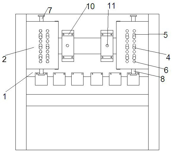
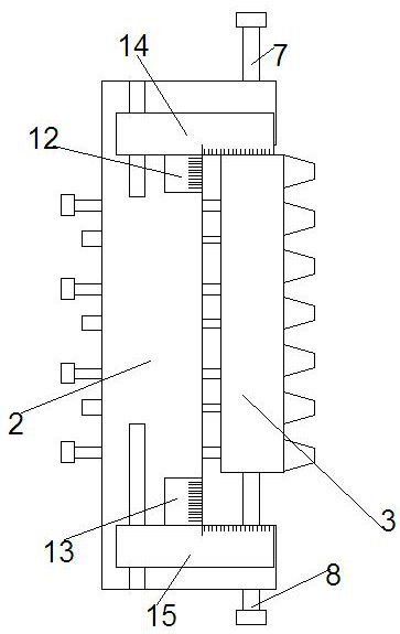
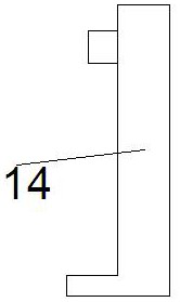
[0018] Such as Figure 1-3 As shown, the present invention is a bending machine with a gear synchronous drive mechanism, including a frame and a workbench. The frame on the workbench is provided with an upper frame 1 that drives the upper bending mold to move up and down. A fixed seat 2 parallel to the upper frame 1 is provided on both sides of the frame near the position of the upper frame 1, and a mounting groove is arranged on each fixed seat 2 opposite to the back of the upper frame 1. Two racks 3 They are respectively arranged in two installation grooves, several threaded holes are arranged on the rack 3, two vertical rows of fixed threaded holes are arranged...


PUM


Abstract

The invention discloses a bending machine with a gear synchronous drive mechanism, which includes a frame and a workbench. The frame on the workbench is provided with an upper frame, and both sides of the frame are provided with fixing seats. There are mounting grooves on each of the fixing bases, and two racks are respectively arranged in the two mounting grooves. There are several threaded holes on the racks, and two vertical rows of fixed threaded holes are arranged on the mounting grooves. There is a waist-shaped hole between two adjacent fixed threaded holes. The adjusting screw is screwed into the hole on the back of the rack through the waist-shaped hole, and the side positioning screw is screwed into the fixed threaded hole to position the rack. Upper and lower positioning screws are respectively arranged at the upper and lower ends of the installation groove, the teeth on the front of the rack mesh with the teeth on the gears at both ends of the gear shaft, and the gear shaft is fixed on the back of the upper frame through two bearing seats. The invention has simple structure and reasonable design, can synchronously drive the upper frame, effectively avoids the swinging of the upper frame, prolongs the service life of the mould, and reduces the maintenance cost.

Description

technical field [0001] The invention relates to a bending machine, in particular to a bending machine with a gear synchronous drive mechanism. Background technique [0002] When the bending machine is working, the upper mold is driven out of sync and swings. It is difficult for the operator to find out in time when the swing is slight. When the swing amplitude becomes larger, the wear of some parts is more serious. Contents of the invention [0003] In order to solve the above problems, the present invention provides a bending machine with a gear synchronous drive mechanism that can reduce wear, reduce maintenance costs, and prolong the service life of the mold. [0004] In order to achieve the above object, the present invention is achieved through the following technical solutions: [0005] The present invention is a bending machine with a gear synchronous drive mechanism, including a frame and a workbench. The frame on the workbench is provided with an upper frame that...

Claims


Application Information

Patent Timeline
IPC IPC(8): B30B1/24B30B15/00B30B15/04
CPCB30B1/24B30B15/0023B30B15/044
Inventor 陶亚鑫
Owner 马鞍山茂丰重工机械制造有限公司
Learn More