
Electromagnetic steering engine and aircraft

A technology of aircraft and steering gear, applied in the field of bionic robots, can solve problems such as poor autonomous flight capability, unstable flight, and difficulty in maintaining stable flight

Pending Publication Date: 2019-11-29
BIONIWINGS BEIJING TECH CO LTD
View PDF0 Cites 3 Cited by
  • Summary
  • Abstract
  • Description
  • Claims
  • Application Information

AI Technical Summary

Problems solved by technology

[0002] The bionic flapping-wing aircraft has a development history of more than 30 years, but due to technical difficulties such as low load capacity and poor autonomous flight capability brought about by the flapping-wing flight method, commercial bionic flapping-wing aircraft are struggling
The flight attitude of the existing bionic flapping-wing aircraft is very unstable. Even with the cooperation of the remote control, it is difficult to maintain a stable flight for a few minutes
[0003] Therefore, the existing bionic flapping-wing aircraft has the technical problem of unstable flight

Method used


Image

  • Electromagnetic steering engine and aircraft
  • Electromagnetic steering engine and aircraft
  • Electromagnetic steering engine and aircraft

Examples


Embodiment Construction

[0036] In order to make the purpose, technical solution and advantages of the present application clearer, the present application will be further described in detail below in conjunction with the accompanying drawings and embodiments. It should be understood that the specific embodiments described here are only used to explain the present application, and are not intended to limit the present application.

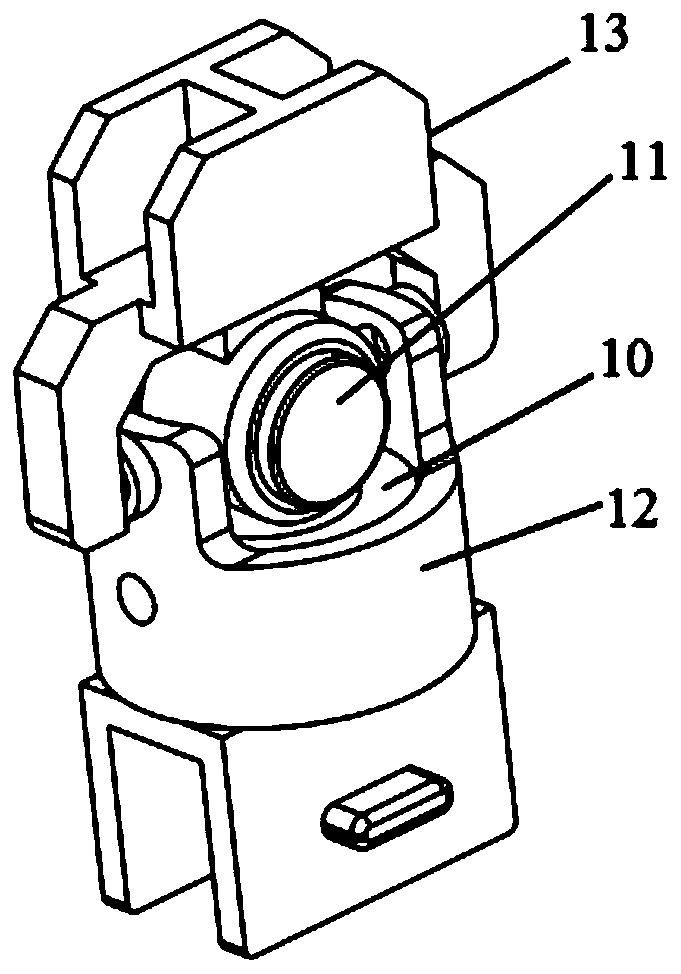
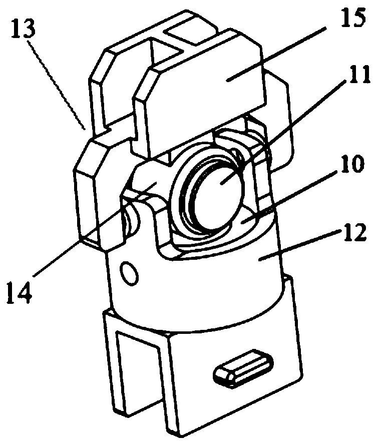
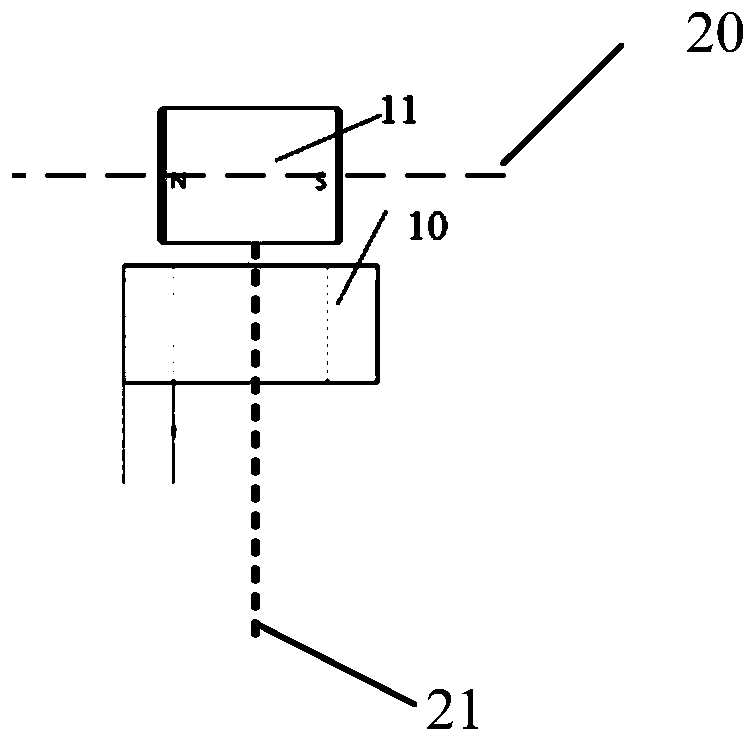
[0037] In one embodiment, such as figure 1 As shown, an electromagnetic steering gear is provided, and the electromagnetic steering gear includes: a driving coil 10, a permanent magnet 11, a coil fixing frame 12, and a permanent magnet fixing frame 13;

[0038] The permanent magnet 11 is installed in the through hole of the permanent magnet holder 13, and the drive coil 10 is installed in the through hole of the coil holder 12; the permanent magnet 11 is outside the drive coil 10 ; The permanent magnet fixing frame 13 is rotationally connected with the coil fixing frame 1...


PUM


Abstract

The invention relates to an electromagnetic steering engine and an aircraft. The electromagnetic steering engine comprises a driving coil, a permanent magnet, a coil fixing mount and a permanent magnet fixing mount, wherein the permanent magnet is installed in the through hole of the permanent magnet fixing mount; the driving coil is installed in the through hole of the coil fixing mount; the permanent magnet is positioned out of the driving coil; the permanent magnet fixing mount is rotatably connected with the coil fixing mount through a rotary shaft; and when the permanent magnet rotates, the permanent magnet fixing mount is driven to synchronously rotate. After the driving coil is electrified, generated electromagnetic force acts on the permanent magnet, so that the permanent magnet generates large-angle rotation, and therefore, the permanent magnet fixing mount synchronously rotates along with the permanent magnet.

Description

technical field [0001] This application relates to the field of bionic robots, in particular to an electromagnetic steering gear and an aircraft. Background technique [0002] The bionic flapping-wing aircraft has a development history of more than 30 years. However, due to technical difficulties such as low load capacity and poor autonomous flight capability brought about by the flapping-wing flight method, commercial bionic flapping-wing aircraft are struggling. The flight attitude of the existing bionic flapping-wing aircraft is very unstable, even with the cooperation of the remote control, it is difficult to maintain a stable flight for a few minutes. [0003] Therefore, existing bionic flapping-wing aircraft has the technical problem of unstable flight. Contents of the invention [0004] Based on this, it is necessary to address the above-mentioned technical problems and provide an electromagnetic steering gear and aircraft capable of making the bionic flapping-wing...

Claims


Application Information

Patent Timeline
Patent Type & Authority Applications(China)
IPC IPC(8): B64C13/50H02K21/14
CPCB64C13/50H02K21/14B64U10/40
Inventor 敬鹏生刘迎建胡海
Owner BIONIWINGS BEIJING TECH CO LTD
Learn More