Al technical title is built by PatSnap Al team. It summarizes the technical point description of the patent document.
A fuse, a new type of technology, applied to vehicle components, emergency protection devices, circuits or fluid pipelines, etc., can solve problems such as thread failure, instability, and affecting nut screwing, so as to reduce precision requirements, improve service life, The effect of reducing the frequency of replacement
Active Publication Date: 2021-11-16
合肥科维特电气科技有限公司
View PDF0 Cites 0 Cited by
Summary
Abstract
Description
Claims
Application Information
AI Technical Summary
This helps you quickly interpret patents by identifying the three key elements:
Problems solved by technology
Method used
Benefits of technology
Problems solved by technology
[0002] Automotive fuses generally include midi and mega fuses. At present, the mega fuse is connected to the lower cover of the fuse base as follows: a screw and a nut are provided on the lower cover, and a through hole matching the screw is provided at both ends of the length of the mega fuse. Insert the through hole on the mega fuse into the screw, and then limit it on the screw through the nut, so that the mega fuse can be installed, but this installation method has the following defects: that is, when the thread on the screw is in contact with the mega fuse for a long time , under the action of electric arc, it is easy to be burned out, which will cause the thread to fail, thus affecting the normal screwing of the nut on the thread, which may cause the mega fuse to be unable to be limited by the nut, making it in an unstable state
Method used
Image
Click on the blue label to locate the original text in one second.
Reading with bidirectional positioning of images and text.
Examples
Embodiment Construction
[0023] In order to make the technical means, creative features, goals and effects achieved by the present invention easy to understand, the technical solutions in the embodiments of the present invention will be clearly and completely described below in conjunction with the accompanying drawings in the embodiments of the present invention. Obviously, the The described embodiments are only some, not all, embodiments of the present invention. Based on the embodiments of the present invention, all other embodiments obtained by persons of ordinary skill in the art without creative efforts fall within the protection scope of the present invention.
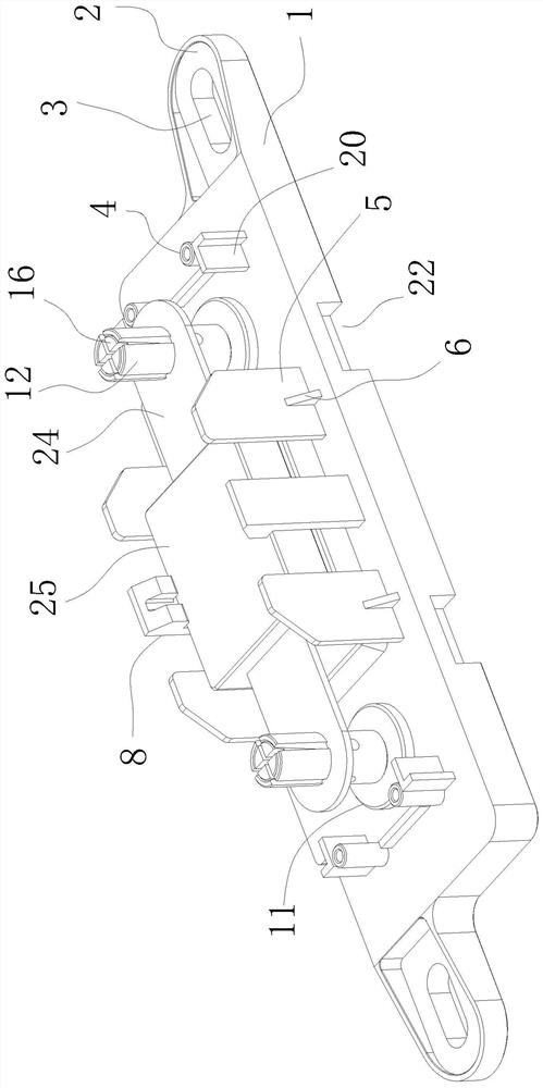
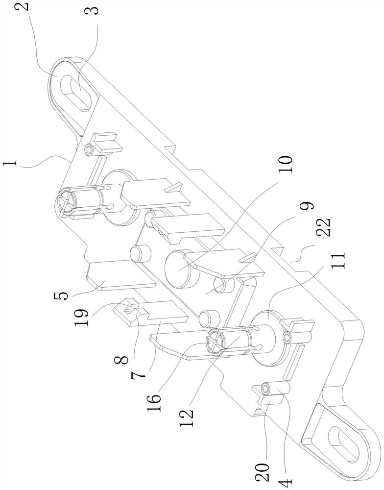
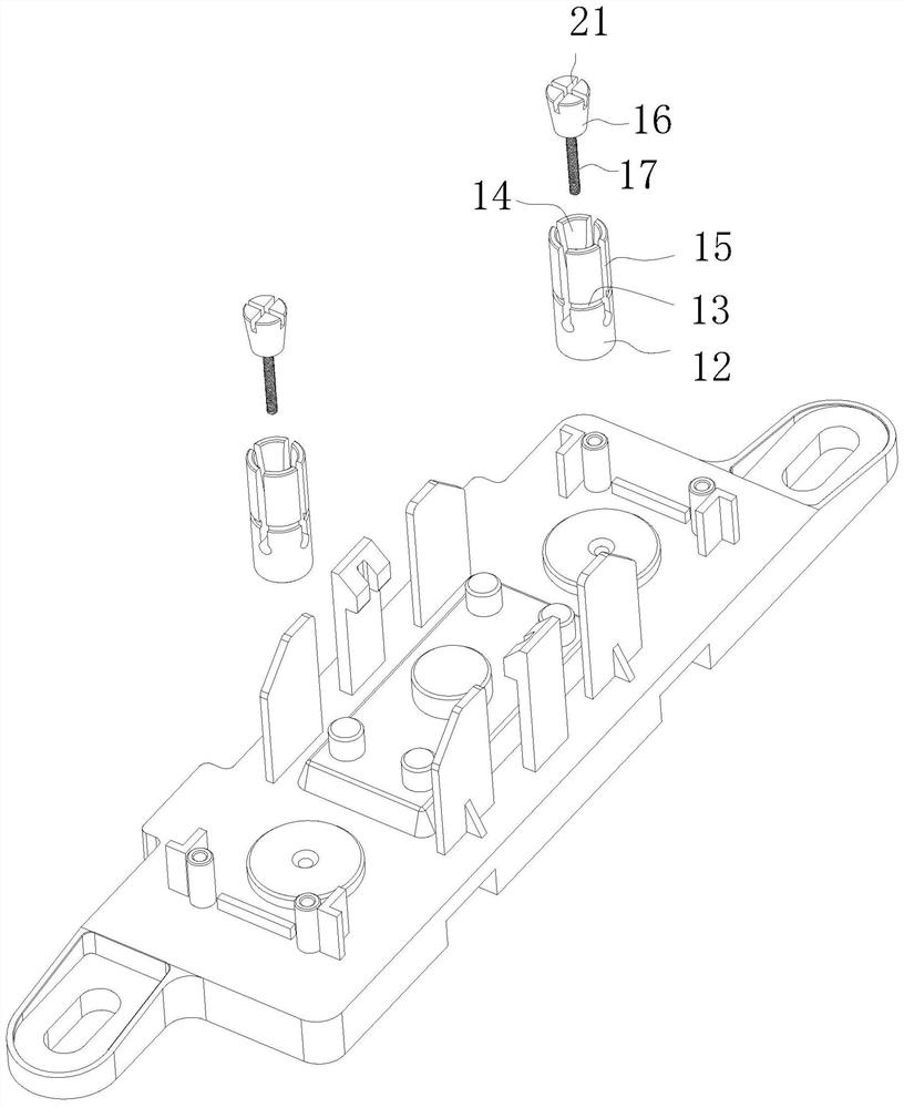
[0024] Such as Figure 1-5 A new type of fuse base for vehicles is shown, which includes a lower cover 1 of the fuse base, a connecting portion 2 is provided at both ends of the lower cover 1 in the length direction, and a connecting hole in the form of a waist hole is provided on the connecting portion 2 3. The top surface of the lowe...
PUM
Abstract
The invention relates to the technical field of automobile electrical appliances, in particular to a new type of fuse base for automobiles, including a lower cover, a connecting part, a connecting hole, a connecting column, a baffle, a clip, a buckle, an elastic pad, a spacer, a protruding part, Limiting column, annular card groove, tapered groove, notch, tapered shaft, screw rod, screw hole. The beneficial effects of the present invention are as follows: the through holes on the fuse are engaged in the annular slots of the two limit posts respectively, and then the cone shaft is rotated by an external tool, and the thread of the screw rod and the screw hole is screwed together to drive the cone shaft in the cone Sliding in the groove, and expand the limit column to the radial outside, so that the inner wall of the annular card groove is pressed against the through hole of the fuse. Since the tapered groove has a vertical upward force on the tapered shaft, the screw and the screw hole can be formed. Anti-loosening, thereby ensuring that the tapered shaft will not slide in the tapered groove, so that the annular card groove can always be pressed against the inner wall of the through hole of the fuse, and the stability after installation is improved.
Description
technical field [0001] The invention relates to the technical field of automobile electric appliances, in particular to a novel fuse base for automobiles. Background technique [0002] Automotive fuses generally include midi and mega fuses. At present, the mega fuse is connected to the lower cover of the fuse base as follows: a screw and a nut are provided on the lower cover, and a through hole matching the screw is provided at both ends of the length of the mega fuse. Insert the through hole on the mega fuse into the screw, and then limit it on the screw through the nut, so that the mega fuse can be installed, but this installation method has the following defects: that is, when the thread on the screw is in contact with the mega fuse for a long time , Under the action of arc, it is easy to be burned out, which will cause the thread to fail, thus affecting the normal screwing of the nut on the thread, which may cause the mega fuse to be unable to be limited by the nut, maki...
Claims
Application Information
Patent Timeline
Application Date:The date an application was filed.
Publication Date:The date a patent or application was officially published.
First Publication Date:The earliest publication date of a patent with the same application number.
Issue Date:Publication date of the patent grant document.
PCT Entry Date:The Entry date of PCT National Phase.
Estimated Expiry Date:The statutory expiry date of a patent right according to the Patent Law, and it is the longest term of protection that the patent right can achieve without the termination of the patent right due to other reasons(Term extension factor has been taken into account ).
Invalid Date:Actual expiry date is based on effective date or publication date of legal transaction data of invalid patent.
