Movable lifting machine device capable of being cascaded in groups and control method thereof

A control method and lift technology, applied in lifting devices, mobile jacks, etc., can solve problems such as poor adaptability of lifts, inconvenience for maintenance companies, limited lifting weight of lifts, etc., and achieve the effect of expanding the scope of application

Active Publication Date: 2019-12-03
MIT AUTOMOBILE SERVICE
View PDF6 Cites 2 Cited by
  • Summary
  • Abstract
  • Description
  • Claims
  • Application Information

AI Technical Summary

Problems solved by technology

The original heavy-duty vehicle maintenance method is to repair the trench. When the vehicle is repaired for the chassis, it needs to open the trench for maintenance. However, the ordinary lift has limited lifting weight or adopts a fixed working method, which is very difficult for maintenance. Inconvenience to the business
This requires the development of a new type of mobile lift, but the current mobile lifts on the market often

Method used


Image

  • Movable lifting machine device capable of being cascaded in groups and control method thereof

Examples


Embodiment 1

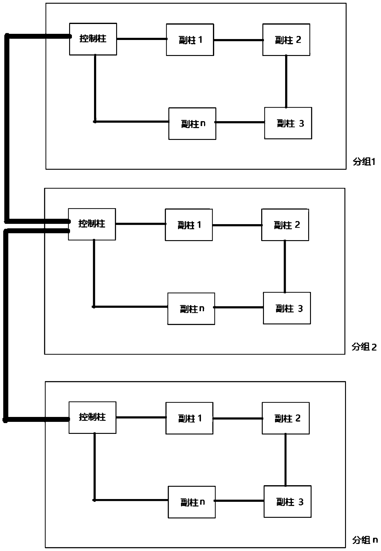
[0032] See attached figure 1 , a mobile lift device that can be grouped and cascaded, including several groups, each group is provided with several lifting columns, and the lifting columns in each group include a main control column and n auxiliary columns ;

[0033] The main control column in each group establishes a communication connection with all the auxiliary columns in the group through communication cables or wirelessly, and the auxiliary column is responsible for collecting the height and key information of the auxiliary column and sending them to the main control column in the group. The main control column controls the operation of all lifting columns in the same group according to the summarized information;

[0034] The lifting columns work based on the motor-hydraulic method. Each lifting column includes a control module, a position sensor and a button; the main control column can set the working mode of the lifting column in this group as single column, local c...

Embodiment 2

[0038] The control method adopted by a mobile lift device that can be grouped and cascaded described in Embodiment 1 includes the following steps:

[0039] (1) Group setting: Group setting is performed when a mobile lift device that can be grouped and cascaded leaves the factory, and the lifting columns in each group are numbered;

[0040] (2) Set the mode through the main control column in each group: when it is set to the single column mode, the button of a certain lifting column can only control the lifting of the lifting column; when it is set to the group mode, any lifting column The buttons of the lifting column can control the lifting of the lifting column; when it is set to the cascade mode, the buttons of any lifting column in the cascading group can control the lifting columns in all groups to perform synchronous lifting;

[0041] (3) Determination of the total control column in different modes: in single column mode, the total control column is the single lifting co...


PUM


Abstract

The invention provides a movable lifting machine device capable of being cascaded in groups and a control method of the movable lifting machine device. The device comprises a plurality of groups, a plurality of lifting columns are arranged in each group, and the lifting columns in each group comprise a main control column and n auxiliary columns. The control method comprises the steps of grouping,setting modes, determining a main control column in different modes and implementing an action mechanism. The beneficial effects of the present invention are that according to the movable lifting machine device and the control method thereof, by adopting the basically same specifications of the lifting columns and the same control program, the switching among a single-column mode, a local group mode and a cascade mode can be realized; a set of devices which can adapt to different place demands can be combined simply, and when the requirement is larger than the maximum number of the lifting columns allowed by each set, a communication channel is additionally established, the cascade operation of several sets of lifting machines is formed, and the purpose of synchronous operation of more lifting columns is achieved.

Description

technical field [0001] The invention belongs to the technical field of automobile maintenance devices, and relates to a mobile vehicle lift and a control method thereof, in particular to a mobile lift device capable of grouping and cascading and a control method thereof. Background technique [0002] With the continuous development of the automobile society and the increasing number of automobiles, automobile maintenance companies are increasingly emphasizing maintenance efficiency. The original heavy-duty vehicle maintenance method is to repair the trench. When the vehicle is repaired for the chassis, it needs to open the trench for maintenance. However, the ordinary lift has limited lifting weight or adopts a fixed working method, which is very difficult for maintenance. Businesses are inconvenient. This requires the development of a new type of mobile lift, but the current mobile lifts on the market often use a fixed number of columns, a control column, and several contr...

Claims


Application Information

Patent Timeline
IPC IPC(8): B66F5/04
CPCB66F5/04
Inventor 栾焕民
Owner MIT AUTOMOBILE SERVICE
Why Eureka
Try Eureka