
Miniature camera module

A technology of camera module and lighting module, applied in the field of camera, can solve the problem that miniaturization cannot be easily achieved, and achieve the effect of wide viewing angle

Active Publication Date: 2019-12-03
SPRING RAINBOW OPTICS CO LTD
View PDF28 Cites 0 Cited by
  • Summary
  • Abstract
  • Description
  • Claims
  • Application Information

AI Technical Summary

Problems solved by technology

Therefore, the design cannot easily achieve the purpose of miniaturization

Method used


Image

  • Miniature camera module
  • Miniature camera module
  • Miniature camera module

Examples


Embodiment Construction

[0055] The following descriptions of the various embodiments refer to the accompanying drawings to illustrate specific embodiments in which the present invention can be practiced. The directional terms mentioned in the present invention, such as "up", "down", "front", "back", "left", "right", "inside", "outside", "side", etc., are for reference only The orientation of the attached schema. Therefore, the directional terms used are used to illustrate and understand the present invention, but not to limit the present invention. Before describing the specific implementation of the present invention in detail, the technical principles and terminology of the present invention will be introduced here.

[0056] In the drawings, elements having a similar structure are denoted by the same reference numerals.

[0057] The content of the present disclosure will be described in detail below with reference to embodiments in conjunction with the accompanying drawings.

[0058] With respec...


PUM


Abstract

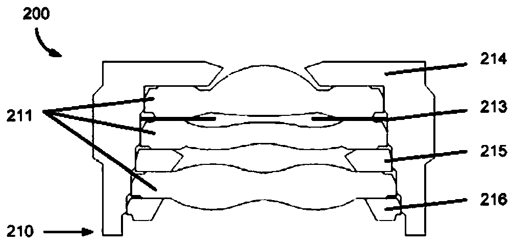
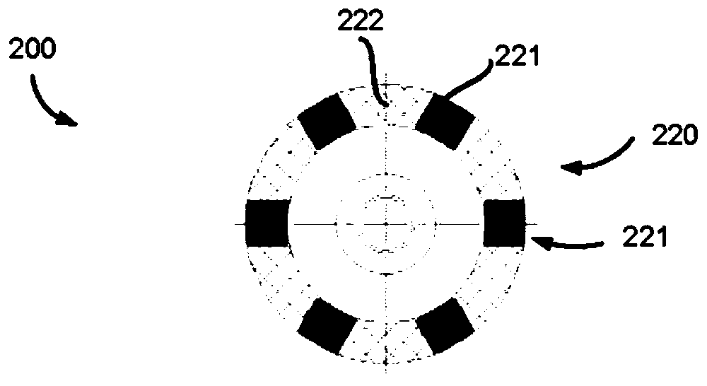
A miniature camera module is provided. The camera module includes a lens assembly and an illuminating module. The lens assembly includes a plurality of lenses and a lens barrel disposed around the lenses for supporting the lenses. The lens assembly includes an incident surface, an emergent surface and a lateral surface. The lens barrel includes a bearing part parallel to the lenses, and the bearing part is disposed on the emergent surface of the lens assembly and is not disposed on the incident surface of the lens assembly. The illuminating module includes at least one light source and an annular circuit board, and disposed on the incident surface of the lens assembly. The invention mainly aims to provide a miniature camera module with a wide view.

Description

[0001] Related applications [0002] This application claims priority under 35 USC 119(e) to US Provisional Patent Application Serial No. 62 / 675,867, filed May 24, 2018, the contents of which are hereby incorporated by reference in their entirety. technical field [0003] The invention relates to the field of camera technology, in particular to a miniaturized camera module with a wide viewing angle. Background technique [0004] A common camera module is mainly composed of a lens assembly 210 and an image sensor 230 (image sensor), such as Figure 1A , Figure 1B shown. The lens assembly 210 includes a lens barrel 212 (lens barrel), a lens 211 (lens), and a light shielding film 213 (light shielding film, from or obtained), spacer ring 215 (spacer), rear cover 216 (retainer) and other components. In a common design, the supporting portion 214 of the lens barrel 212 is located near the first lens away from the image sensor 230 to facilitate assembly into a compact module...

Claims


Application Information

Patent Timeline
Patent Type & Authority Applications(China)
IPC IPC(8): G02B13/06G02B7/02
CPCG02B13/06G02B7/021G02B23/2484H04N23/56H04N23/55G02B13/0015G02B1/041H04N23/57
Inventor 卓宏章郑煜腾
Owner SPRING RAINBOW OPTICS CO LTD
Learn More