Pantoscopic zoom lens for projection and projection type display device

A zoom lens and projection technology, applied in the field of zoom lenses, can solve the problems of difficulty in maintaining axial aberration, difficulty in compactness, and difficulty in maintaining optical performance, and achieve the effect of suppressing enlargement and improving portability or usability

Inactive Publication Date: 2010-09-29
FUJI PHOTO OPTICAL CO LTD
View PDF2 Cites 0 Cited by
  • Summary
  • Abstract
  • Description
  • Claims
  • Application Information

AI Technical Summary

Problems solved by technology

[0008] Among fixed-magnification projection lenses mounted on rear projector devices, etc., lenses with a half angle of view of 45 degrees or more are known. It is difficult to maintain good optical performance from the wide-angle end to the telephoto end, and it is particularly difficult to maintain axial aberrations such as spherical aberration common to the viewing angle (image height), and distortion or curvature of field that vary with the viewing angle. The balance of off-axis aberrations, and it is difficult to make good corrections for the above-mentioned aberrations
In addition, there is also the problem that compaction is difficult due to the large lens system of the lens group arranged on the magnification side, and it has not been realized.

Method used


Image

  • Pantoscopic zoom lens for projection and projection type display device
  • Pantoscopic zoom lens for projection and projection type display device
  • Pantoscopic zoom lens for projection and projection type display device

Examples


Embodiment 1

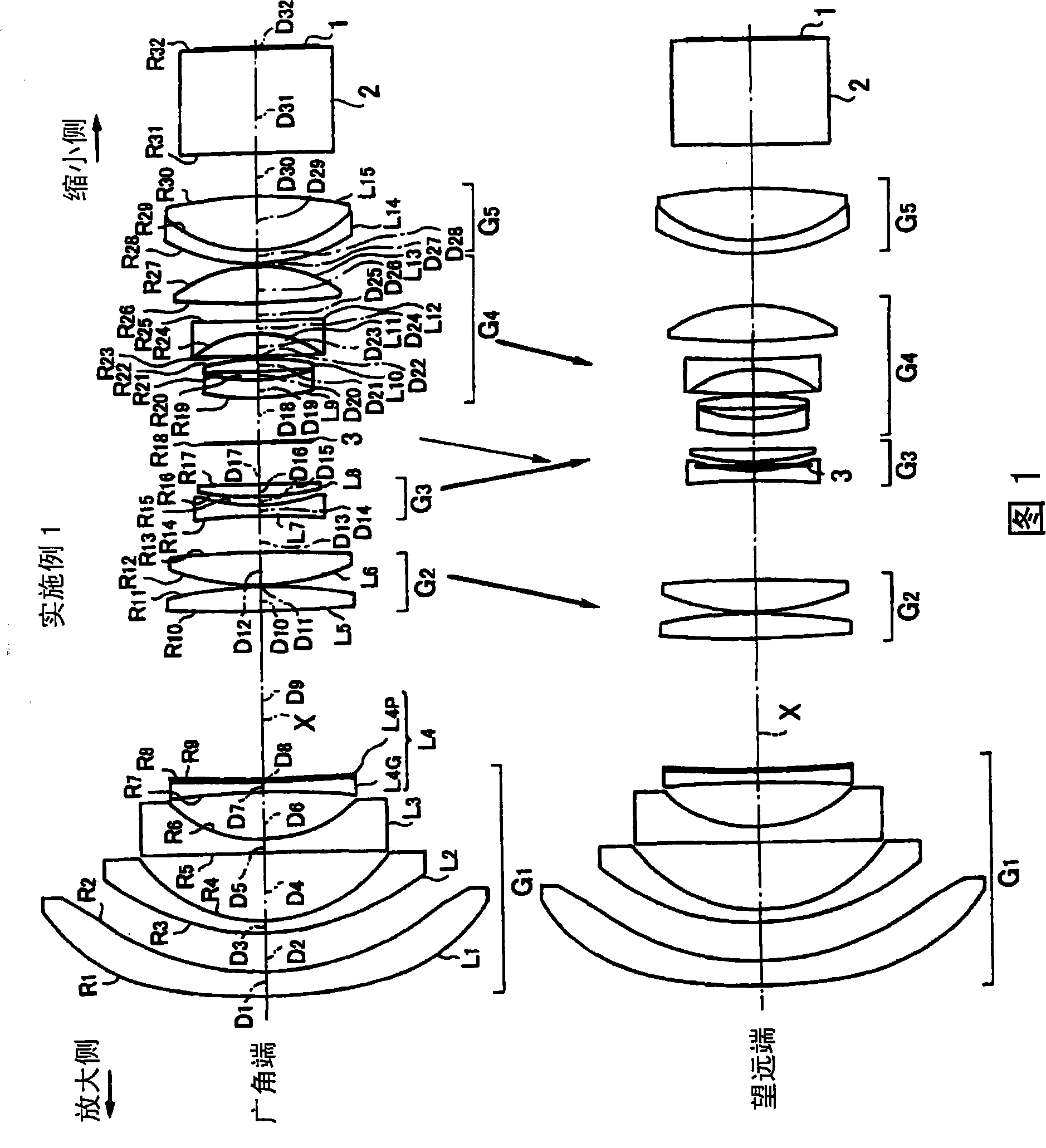
[0044] like figure 1 As shown, the wide-angle zoom lens for projection according to Example 1 is arranged in order from the magnification side in the arrangement at the wide-angle end: lens group G for focusing 1 , which is fixed and has a negative refractive power when zooming; the lens group G is moved when zooming 2 , G 3 ;Aperture stop 3, can move independently when zooming; move lens group G when zooming 4 ; and the lens group G for fixing the pupil position 5 , it is fixed and has a positive refractive power when zooming; and, the reduction side is set as telecentric. In addition, in the pupil position fixing lens group G 5 The image display surface 1 and the glass block 2 of the light valve are arranged in order from the reduction side. It should be noted that moving the lens group G during the 3 zooms 2 ~G 4 They are configured to move independently of each other when zooming.

[0045] The above-mentioned focusing lens group G 1 , as mentioned above, consists ...

Embodiment 2

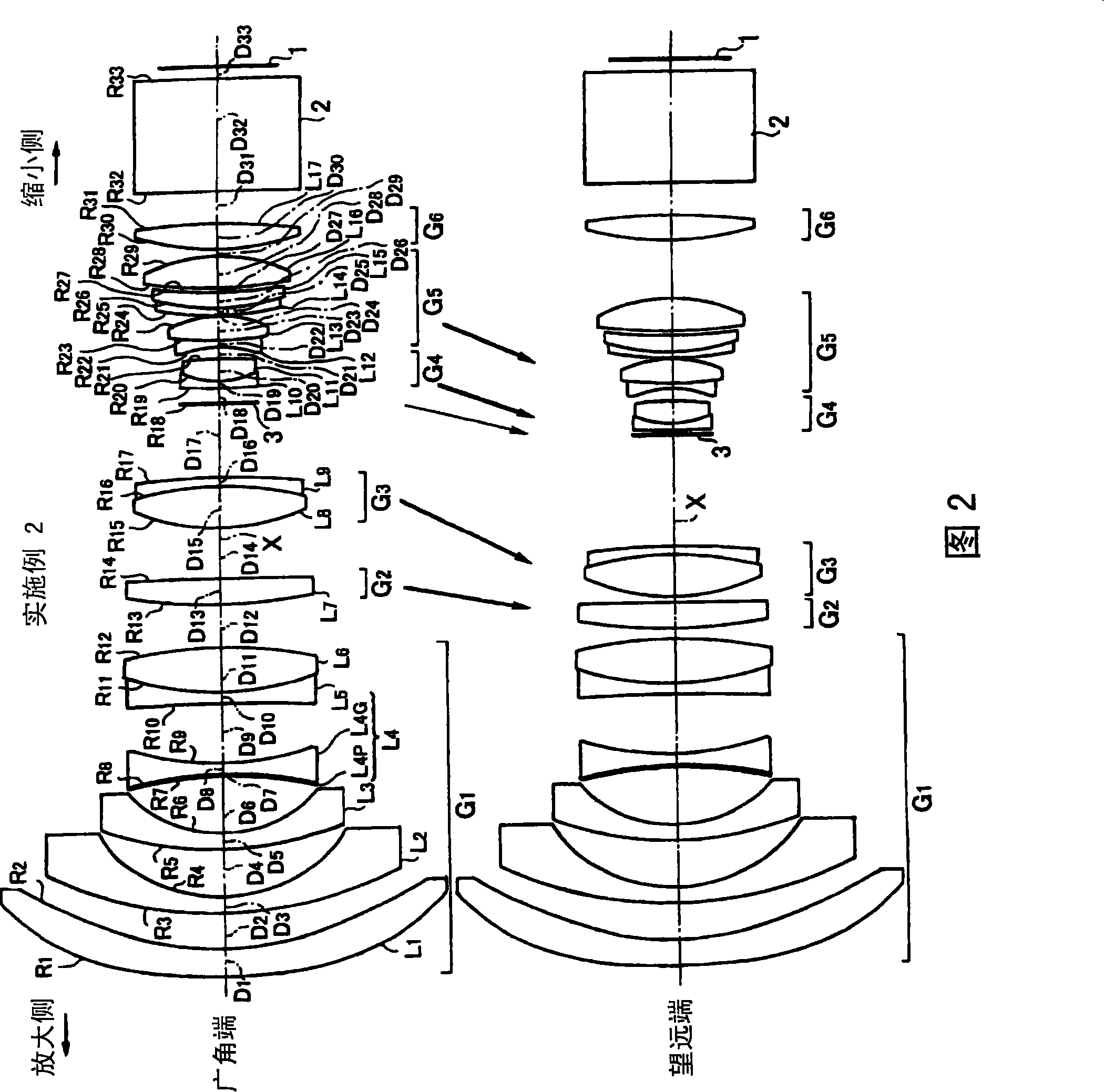
[0110] like figure 2 As shown, the wide-angle zoom lens for projection according to Example 2 is arranged sequentially from the magnification side in the arrangement at the wide-angle end: a focusing lens group G that is fixed and has a negative refractive power when changing magnification 1 ;Move the lens group G when zooming 2 , G 3 ,; independently movable aperture stop 3 during zooming; moving lens group G during zooming 4 , G 5 ; and a lens group G for fixing the pupil position that is fixed and has a positive refractive power when zooming 6 ; and, set the reduction side to be telecentric. In addition, in the pupil position fixing lens group G 6 The image display surface 1 and the glass block 2 of the light valve are arranged in order from the reduction side. It should be noted that when moving the lens group G at 4 zooms 2 ~G 5 are constructed to move independently of each other when zooming.

[0111] The above-mentioned focusing lens group G 1, consisting of ...


PUM


Abstract

The invention provides a projection pancratic pantoscope which structure is compact and which half view angle is over 45 DEG on the wide angle end, and a projection-type display device carrying the projection pancratic pantoscope. From the amplification side, the invention comprises: a set of focusing lenses (G<1>) having fixed negative refraction force during varying the power; three sets of room movable lenses (G<2>-G<4>) capable of independently moving during varying the power; a set of lenses (G<5>) which has fixed positive refraction force during varying the power for fixing the pupil position; and the reduction side is telecentric. The set of focusing lens (G<1>) is composed of four pieces of negative lenses (L<1>-L<4>) which are arranged continuously from the most amplification side, wherein, both sides of the first lens (L<1>) and the reduced side of the fourth lens (L<4>) are configured as aspheric surface.

Description

technical field [0001] The present invention relates to a zoom lens used as a projection lens of a projector device, etc., and particularly relates to enlarging and projecting an original image formed by a light valve such as a liquid crystal display element or a DMD (digital micro mirror device: digital micro mirror device) on a A wide-angle zoom lens for projection on a screen, and a projection display device equipped with the wide-angle zoom lens for projection. Background technique [0002] A so-called front projection type projector that projects an image onto a screen in front of the device has been widely used in recent years for school education, corporate training, presentations, and the like. [0003] A projection lens mounted on such a front projection type projection device is required to have a variable magnification function (zoom function), have a compact configuration, and have a wide viewing angle in consideration of portability of the device and compatibili...

Claims


Application Information

Patent Timeline
Patent Type & Authority Patents(China)
IPC IPC(8): G02B15/177G02B15/16G02B13/18G03B21/14
Inventor 佐渡谦造
Owner FUJI PHOTO OPTICAL CO LTD
Why Eureka
Try Eureka