Shooting optical lens unit
An optical lens and lens technology, applied in the field of optical lenses, can solve the problems of insufficient lens shape setting, insufficient distribution of lens refractive power ratio, insufficient light transmission, etc., and achieve the effect of excellent imaging quality.
- Summary
- Abstract
- Description
- Claims
- Application Information
AI Technical Summary
Problems solved by technology
Method used
Image

Examples
no. 1 approach
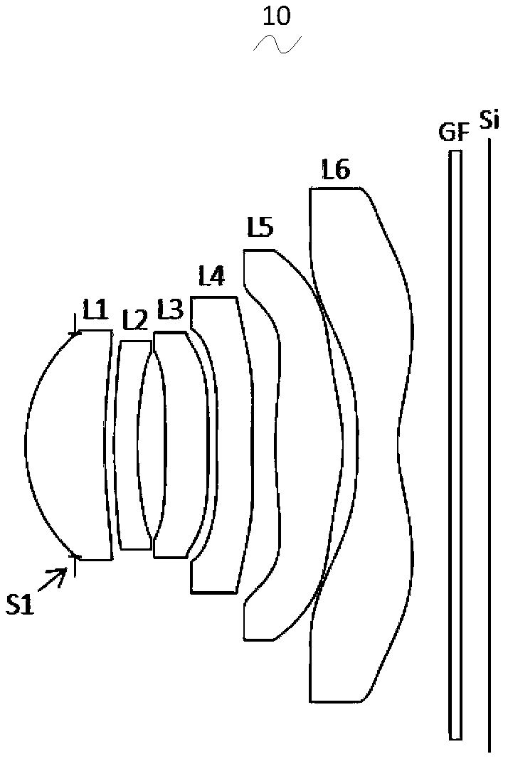
[0026] Referring to the accompanying drawings, the present invention provides an imaging optical lens 10 . figure 1 Shown is the imaging optical lens 10 of the first embodiment of the present invention, and the imaging optical lens 10 includes six lenses. Specifically, the imaging optical lens 10 includes, from the object side to the image side in sequence: an aperture S1, a first lens L1, a second lens L2, a third lens L3, a fourth lens L4, a fifth lens L5, and a sixth lens. Lens L6. In this embodiment, optical elements such as a glass plate GF can be arranged between the sixth lens L6 and the image plane Si, wherein the glass plate GF can be a glass cover, or a filter with functions such as IR cut-off filtering. ), of course, in other possible implementation manners, the glass plate GF can also be arranged at other positions.
[0027] In this embodiment, the first lens L1 has a positive refractive power, its object side is convex outward, and its image side is concave; the...
no. 2 approach
[0108] Figure 5 It is a schematic structural diagram of the imaging optical lens 20 in the second embodiment. The second embodiment is basically the same as the first embodiment, and the meanings of symbols are the same as those of the first embodiment, and only the differences are listed below.
[0109] Table 3 shows the object side and image side curvature radii r of the first lens L1 to the sixth lens L6 constituting the imaging optical lens 20 in the second embodiment, the on-axis thickness of the lenses or the on-axis distance d between the lenses, the refraction rate nd and Abbe number vd. Table 4 shows the aspherical surface data of each lens in the imaging optical lens 20 according to the second embodiment of the present invention.
[0110] It should be noted that, in this embodiment, the units of the radius of curvature and the thickness on the axis are mm.
[0111] 【table 3】
[0112]
[0113] 【Table 4】
[0114]
[0115] In the following Table 7, the values...
no. 3 approach
[0119] Figure 9 It is a schematic structural diagram of the imaging optical lens 30 in the third embodiment. The third embodiment is basically the same as the first embodiment, and the meanings of symbols are the same as those of the first embodiment, and only the differences are listed below.
[0120] Table 5 shows the object-side and image-side curvature radii r of the first lens L1 to the sixth lens L6 constituting the imaging optical lens 30 in the third embodiment, the on-axis thickness of the lenses or the on-axis distance d between the lenses, the refraction rate nd and Abbe number vd. Table 6 shows aspherical surface data of each lens in the imaging optical lens 30 of the third embodiment.
[0121] It should be noted that, in this embodiment, the units of the radius of curvature and the thickness on the axis are mm.
[0122] 【table 5】
[0123]
[0124]
[0125] 【Table 6】
[0126]
[0127] In the following Table 7, the values of f, f1, f2, f3, f4, f5, an...
PUM
 Abstract
Description
Claims
Application Information