optical lens

An optical lens and lens technology, applied in the field of optical lenses, can solve the problems of small field of view and small focal length, and achieve the effect of large field of view

Active Publication Date: 2022-06-24
JIANGXI LIANCHUANG ELECTRONICS CO LTD
View PDF5 Cites 0 Cited by
  • Summary
  • Abstract
  • Description
  • Claims
  • Application Information

AI Technical Summary

Problems solved by technology

Although the telephoto lens has a long focal length, but the field of view is small, it is generally used for capturing and observing long-distance objects; although the wide-angle lens has a large field of view, but the focal length is small, it is generally used for capturing and observing close-range objects; therefore, it is necessary to design a compatible The function of telephoto lens and wide-angle lens, and has a large aperture, large field of view and high resolution optical lens, to replace the traditional multiple lenses with a single function in the automatic driving assistance system

Method used


Image

  • optical lens
  • optical lens
  • optical lens

Examples


Embodiment 1

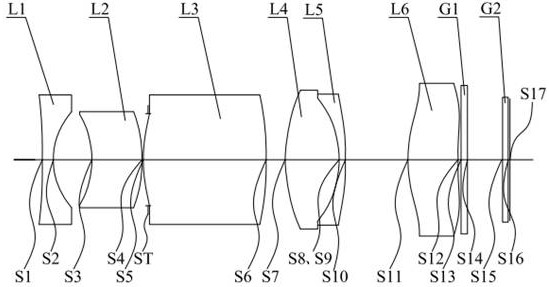
[0091] see figure 1 , which is a schematic structural diagram of the optical lens provided in Embodiment 1 of the present invention. The optical lens sequentially includes from the object side to the imaging plane along the optical axis: a first lens L1, a second lens L2, a diaphragm ST, and a third lens. L3, the fourth lens L4, the fifth lens L5, the sixth lens L6, the filter G1, and the protective glass G2.

[0092] The first lens L1 has negative refractive power, the object side S1 is concave, and the image side S2 is concave; the second lens L2 has negative refractive power, and its object side S3 is concave, and the image side S4 is convex; diaphragm ST; The third lens L3 has positive refractive power, and both the object side S5 and the image side S6 are convex; the fourth lens L4 has positive refractive power, and both the object side S7 and the image side S8 are convex; the fifth lens L5 has a negative focus degree, its object side S9 is concave, and its image side S1...

Embodiment 2

[0105] see Image 6 , which is a schematic structural diagram of the optical lens provided in Embodiment 2 of the present invention. The optical lens sequentially includes from the object side to the imaging plane along the optical axis: a first lens L1, a second lens L2, a third lens L3, a diaphragm ST, the fourth lens L4, the fifth lens L5, the sixth lens L6, the filter G1, and the protective glass G2.

[0106] The first lens L1 has negative refractive power, the object side S1 is concave, and the image side S2 is concave; the second lens L2 has negative refractive power, the object side S3 is concave, and the image side S4 is convex; the third lens L3 It has positive refractive power, and its object side S5 and image side S6 are convex; diaphragm ST; the fourth lens L4 has positive refractive power, and its object side S7 and image side S8 are convex; the fifth lens L5 has negative focus degree, its object side S9 is a concave surface, and its image side S10 is a convex su...

Embodiment 3

[0119] see Figure 11 , which is a schematic structural diagram of the optical lens provided in Embodiment 3 of the present invention. The optical lens sequentially includes from the object side to the imaging plane along the optical axis: a first lens L1, a second lens L2, a third lens L3, a diaphragm ST, the fourth lens L4, the fifth lens L5, the sixth lens L6, the filter G1, and the protective glass G2.

[0120] The first lens L1 has negative refractive power, the object side S1 is concave, and the image side S2 is concave; the second lens L2 has negative refractive power, the object side S3 is concave, and the image side S4 is convex; the third lens L3 It has positive refractive power, and its object side S5 and image side S6 are convex; diaphragm ST; the fourth lens L4 has positive refractive power, and its object side S7 and image side S8 are convex; the fifth lens L5 has negative focus degree, its object side S9 is a concave surface, and its image side S10 is a convex ...


PUM


Abstract

The invention discloses an optical lens, comprising six lenses in total, including: a first lens with negative optical power from the object side to the imaging surface along the optical axis, the object side and the image side are both concave surfaces; degree of the second lens, its object side is concave, the image side is convex; the third lens with positive power, its object side and image side are both convex; the fourth lens with positive power, its object side and image side The sides are all convex; the fifth lens with negative refractive power has a concave surface on its object side and a convex image on its side; the sixth lens with positive refractive power has a convex object on its side and a concave image on its side; The lens and the fifth lens are cemented to form a cemented lens; the effective focal length f of the optical lens and the real image height IH corresponding to the maximum field of view satisfy: 0.55<f / IH<0.65.

Description

technical field [0001] The present invention relates to the technical field of imaging lenses, in particular to an optical lens. Background technique [0002] In recent years, the automatic driving assistance system has developed rapidly, and the image algorithm is also being updated. As the key component of the automatic driving assistance system to obtain external information, the vehicle lens also needs to be introduced to meet the needs of the current stage. [0003] At present, the information acquisition of conventional automatic driving assistance systems in a single direction is usually inseparable from telephoto lenses and wide-angle lenses. Although the telephoto lens has a long focal length, it has a small field of view and is generally used for capturing and observing long-distance objects; although the wide-angle lens has a large field of view, but has a small focal length, it is generally used for capturing and observing close-up objects; therefore, it is neces...

Claims


Application Information

Patent Timeline
Patent Type & Authority Patents(China)
IPC IPC(8): G02B13/06G02B13/18
CPCG02B13/006G02B13/06G02B13/0045
Inventor 陈伟建徐宇轩
Owner JIANGXI LIANCHUANG ELECTRONICS CO LTD
Why Eureka
Try Eureka