imaging lens

An imaging lens and lens technology, applied in the field of imaging lenses, can solve the problems of large defocus amount and difficult to meet the requirements of high-definition resolution of products, and achieve the effect of small defocus amount, clear resolution image power, and large aperture.

Active Publication Date: 2022-04-15
SINTAI OPTICAL SHENZHEN CO LTD +1
View PDF0 Cites 0 Cited by
  • Summary
  • Abstract
  • Description
  • Claims
  • Application Information

AI Technical Summary

Problems solved by technology

The commercially available day and night confocal lens has a large amount of defocus when switching between visible light and infrared working bands, which is difficult to meet the high-definition resolution requirements of the product

Method used


Image

  • imaging lens
  • imaging lens
  • imaging lens

Examples


Embodiment Construction

[0044] In order to make the object, technical solution and advantages of the present invention clearer, the present invention will be further described in detail below in conjunction with the accompanying drawings and embodiments. It should be understood that the specific embodiments described here are only used to explain the present invention, not to limit the present invention.

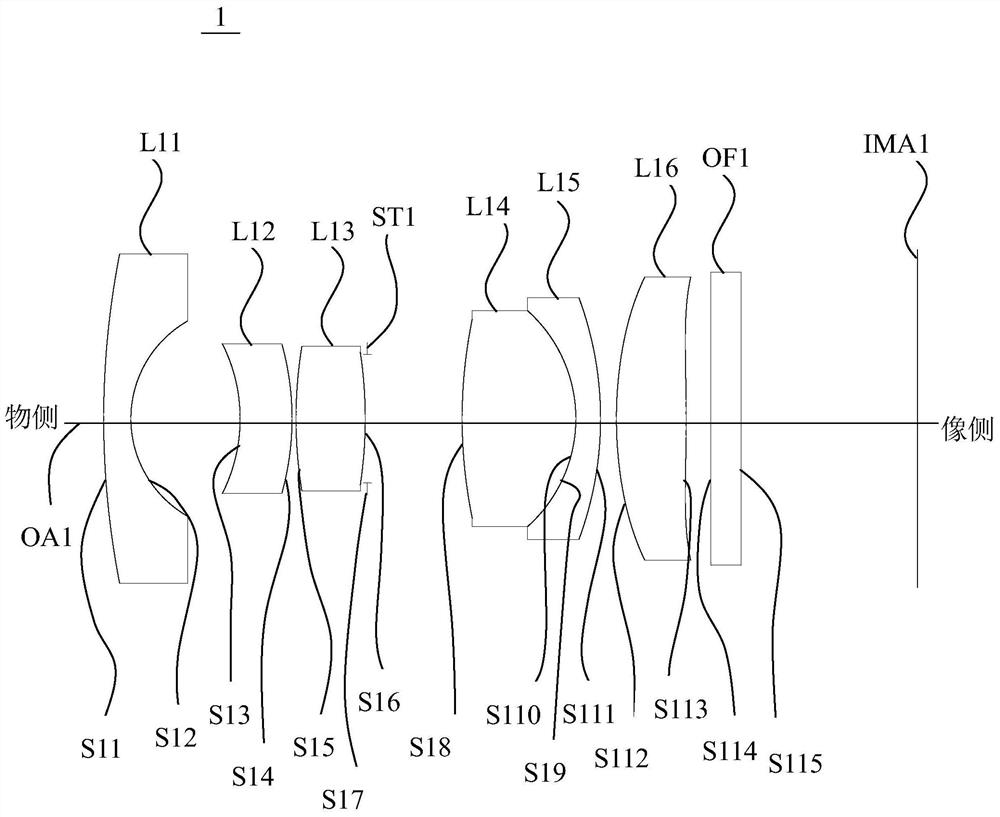
[0045] see figure 1 , figure 1 is a schematic diagram of the lens configuration of the first embodiment of the imaging lens 1 according to the present invention. During imaging, the light from the object side is finally imaged on the imaging surface IMA1. The imaging lens 1 is an infrared confocal lens, and includes in sequence from the object side to the image side along the optical axis OA1: a first lens group including a first lens L11; a second lens group including a second lens L12; a third lens group , including a third lens L13; an aperture ST1; a fourth lens group including a fourth lens...


PUM


Abstract

The invention relates to an imaging lens, which comprises in sequence from the object side to the image side along the optical axis: a first lens, which is a meniscus lens, has negative refractive power, and the object side is convex and the image side is concave; the second lens , is a meniscus lens with negative refractive power, and its object side is concave and its image side is convex; the third lens is a biconvex lens with positive refractive power; the fourth lens has positive refractive power; the fifth lens has negative Refractive power; sixth lens, with positive refractive power.

Description

technical field [0001] The invention relates to an imaging lens. Background technique [0002] With the substantial improvement of the performance of camera devices and the improvement of auxiliary lighting conditions, the trend of many camera systems to develop high-definition and day-night colorization is becoming more and more obvious. Therefore, many new requirements are put forward for the matching lens. The commercially available day and night confocal lens has a large amount of defocus when switching between visible light and infrared working bands, which is difficult to meet the high-definition resolution requirements of the product. Contents of the invention [0003] The technical problem to be solved by the present invention is to provide an imaging lens that has better optical performance and can be used when switching between visible light and infrared working bands, aiming at the defect that the lens of the prior art has a large defocus amount when switching ...

Claims


Application Information

Patent Timeline
Patent Type & Authority Patents(China)
IPC IPC(8): G02B13/18G02B13/14G02B13/06
CPCG02B13/0045G02B13/008G02B13/06
Inventor 付涛
Owner SINTAI OPTICAL SHENZHEN CO LTD
Why Eureka
Try Eureka