Power source apparatus and vehicle with the same

A technology for power supply devices and electrical components, which is applied to electrical devices, power devices, electric vehicles, etc., can solve the problems of large-scale outer casings and increased number of battery blocks, and achieves the maintenance of mechanical strength, high space efficiency, and high space efficiency. The effect of saving labor and time

Active Publication Date: 2011-08-24
SANYO ELECTRIC CO LTD
View PDF5 Cites 71 Cited by
  • Summary
  • Abstract
  • Description
  • Claims
  • Application Information

AI Technical Summary

Problems solved by technology

[0003] However, in this structure, if the number of battery cells is large, the number of battery blocks also increases accordingly.
In addition, as the number of battery cells increases, the number of terminals for detecting the voltage or temperature of each battery cell also increases, and the size of the microcomputer board increases.
Therefore, there is a problem of increasing the size of the exterior case itself as a result of increasing the size of the components accommodated in the electrical case.

Method used


Image

  • Power source apparatus and vehicle with the same
  • Power source apparatus and vehicle with the same
  • Power source apparatus and vehicle with the same

Examples


Embodiment 1

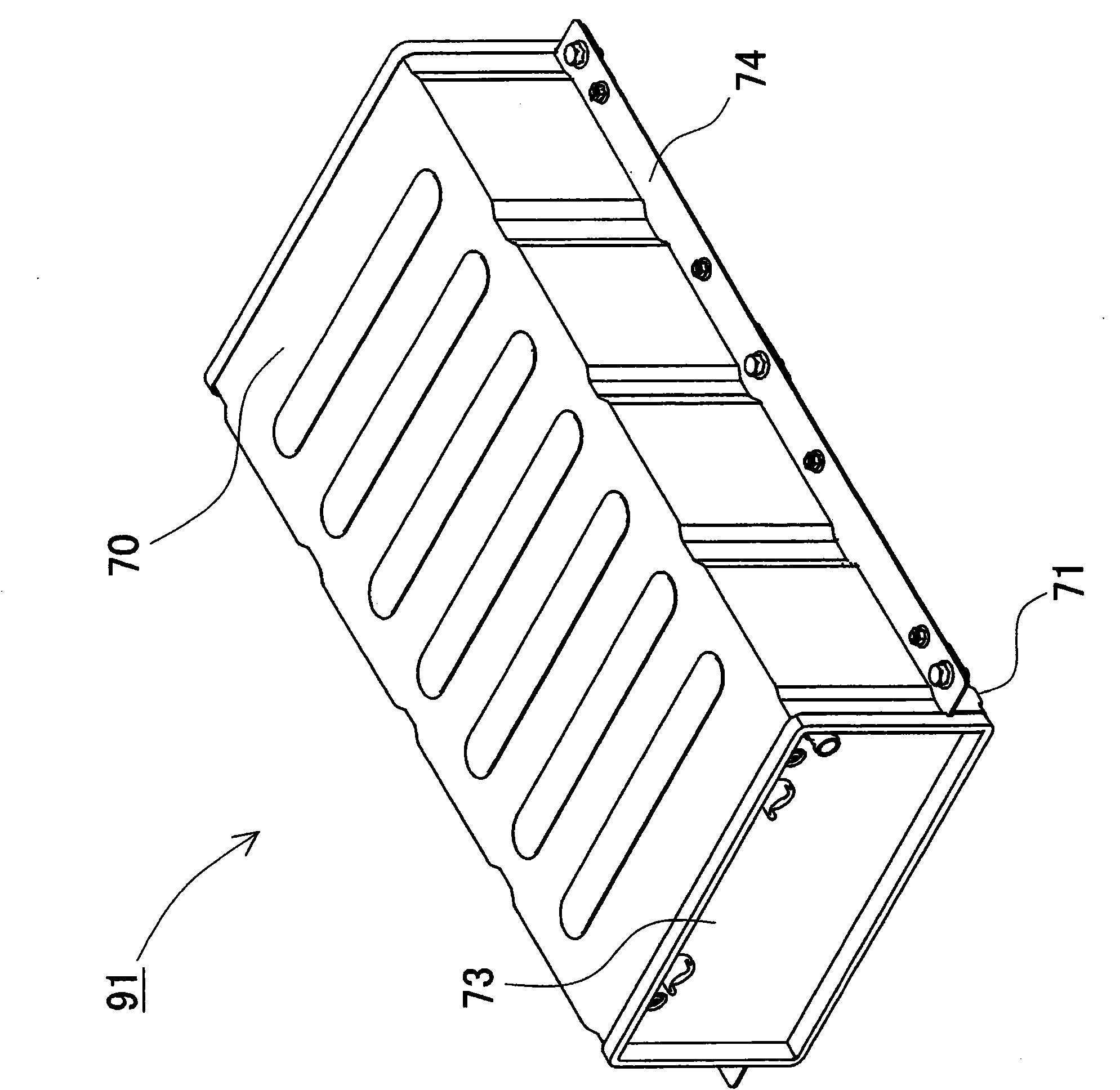
[0123] Figure 3 to Figure 20 A detailed structure of the power supply device 91 according to the first embodiment mounted on the above vehicle is shown in FIG. In the above figure, image 3 is a perspective view of the power supply unit 91, Figure 4 From image 3 The perspective view of the state in which the outer casing 70 is removed from the cover plate, Figure 5 yes Figure 4 Perspective view of block housing 75, Figure 6 yes Figure 5 An exploded perspective view of the block housing 75, Figure 7 yes Figure 6 A perspective view of the battery block 50, Figure 8 is viewed from the back Figure 6 A perspective view of the battery block 50, Figure 9 yes Figure 7 An exploded perspective view of the battery block 50, Figure 10 yes Figure 7 An exploded perspective view of the first end plate 4A portion of the battery stack, Figure 11 yes Figure 8 An exploded perspective view of the second end plate 4B portion of the battery stack, Figure 12 yes F...

Embodiment 2

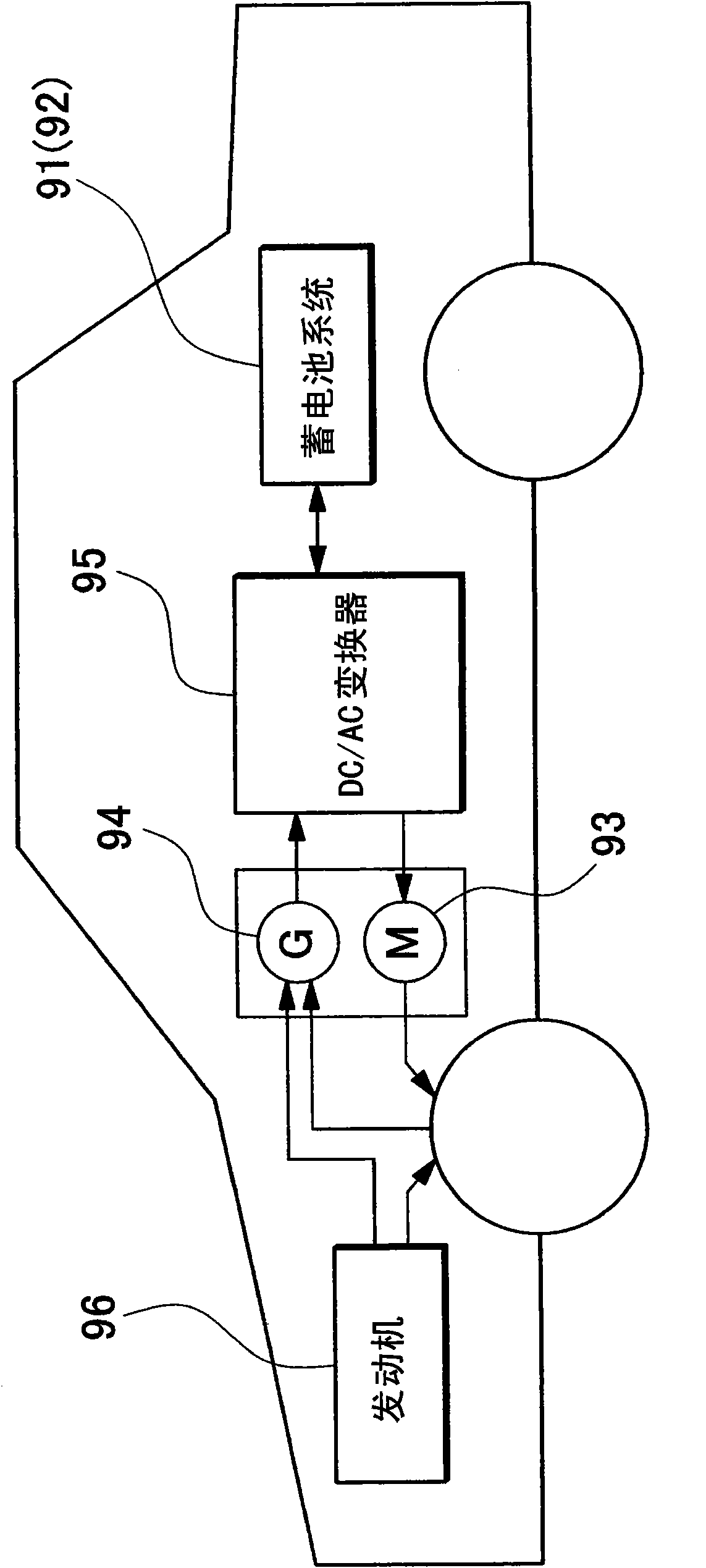
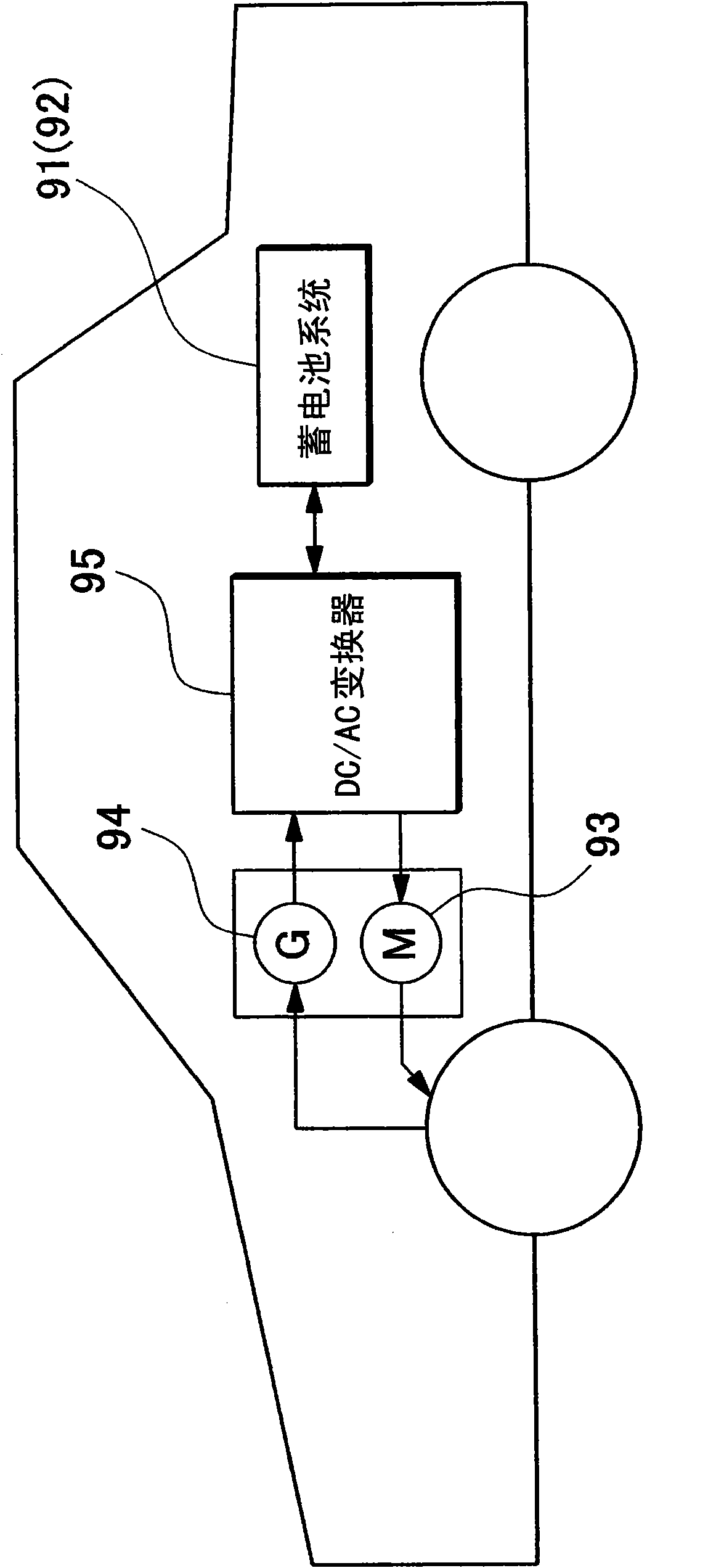
[0166] In addition, if Figure 21 to Figure 25 As shown, the power supply device 92 according to the second embodiment includes: a battery stack 10B formed by stacking battery cells 1 composed of a plurality of prismatic batteries provided with a cooling gap 53; The forced air blowing mechanism 59 for cooling the battery unit 1 by wind; and the exterior case 70B for accommodating the battery stack 10B. The exterior case 70B is composed of an upper case 72B and a lower case 71B, and a flange portion 74B is provided on the lower case.

[0167] In the battery stack 10B, separators 52 are interposed between stacked battery cells 1 . The separator 52 is shaped to form a cooling gap 53 between the battery cells 1 . In addition, in Figure 25 and Figure 26 The separators 52 are connected to the battery cells 1 in a fitting structure on both sides. Adjacent battery cells 1 are laminated by preventing positional displacement of adjacent battery cells 1 by separators 52 connected ...

Embodiment 3

[0185] In the above examples, as the battery unit 1 , a rectangular battery having a box-shaped or plate-shaped outer case was used, but the configuration is not limited to this, and a cylindrical battery unit may also be used. Figure 27 An example of a battery block using cylindrical battery cells 1B as Embodiment 3 is shown in . As shown in the figure, a battery stack 10C in which cylindrical batteries are placed vertically and connected is constructed, placed on a cooling plate 7C, and a block circuit board 60B is disposed on one end surface of the battery stack 10C. An electrical component bracket 62B is disposed on the other end surface, and an electrical component component 63C is disposed on the electrical component bracket 62B. In this configuration, too, there is no need to prepare a dedicated electrical case for accommodating electrical components, and the advantage of simplifying the overall structure can be obtained by arranging and managing the electrical compone...


PUM


Abstract

The invention provides a power source apparatus and a vehicle with the same, capable of furthermore miniaturizing an outer case of the power source apparatus. The power source apparatus is provided with battery blocks 50 made up of a plurality of battery cells 1 connected in battery stacks, and an outer case that holds the battery blocks 50. A block circuit board 60 to control the battery cells 1 that make up each battery stack and electrical components 63 connected to the block circuit board 60 or the battery stack are disposed in the end-planes of each battery stack. With this arrangement, electrical components are disposed in each battery block eliminating the need for a special purpose electrical component case and allowing outer case enlargement to be avoided.

Description

technical field [0001] The present invention mainly relates to a power supply device for large current used as a power supply for driving a motor of a vehicle such as a hybrid vehicle or an electric vehicle, and a vehicle equipped with the power supply device. Background technique [0002] A motor vehicle such as an electric vehicle running with an electric motor or a hybrid vehicle running with both an electric motor and an engine is equipped with a power supply device in which a battery unit is accommodated in an exterior case. In this power supply device, a plurality of battery cells are connected in series to form a battery block having a high output voltage in order to obtain an output for driving the vehicle by using an electric motor. The battery block is accommodated in the exterior case, thereby protecting the battery unit from external impact, and achieving dustproof and waterproof. In addition, in order to properly control the above-mentioned battery cells, it is...

Claims


Application Information

Patent Timeline
Patent Type & Authority Applications(China)
IPC IPC(8): H01M2/10H01M2/20B60L11/18B60K6/28B60L3/00H01M10/48H01M10/60H01M10/613H01M10/617H01M10/625H01M10/643H01M10/647H01M10/651H01M10/652H01M10/653H01M10/6554H01M10/6556H01M10/6557H01M10/6563H01M10/6566H01M10/6569H01M10/658H01M10/663H01M50/209H01M50/213H01M50/264H01M50/284H01M50/289H01M50/505H01M50/51H01M50/512H01M50/569
CPCH01M10/425H01M10/482H01M10/5038H01M2/206Y02E60/12H01M10/5073H01M10/5057H01M10/0525H01M10/5077H01M10/504H01M10/5008H01M10/5053H01M2/0473H01M10/5032H01M10/5016H01M10/5067Y02T10/7011H01M2/1077H01M10/5004H01M10/625H01M10/653H01M10/6563H01M10/647H01M10/6556H01M10/6568H01M10/652H01M10/6554H01M10/617H01M10/6566H01M10/613Y02E60/10H01M50/15H01M50/51H01M50/505H01M50/209H01M50/284H01M50/213H01M50/289H01M50/512H01M50/264H01M50/569
Inventor 浅井康广西原由知大仓计美宫崎裕
Owner SANYO ELECTRIC CO LTD
Why Eureka
Try Eureka