
Rotatable chair leg

A technology of chair legs and swivel sleeves, which is applied in the field of furniture and can solve problems such as inability to align and rotate

Pending Publication Date: 2019-12-13
YUCAI HLDG GROUP
View PDF0 Cites 1 Cited by
  • Summary
  • Abstract
  • Description
  • Claims
  • Application Information

AI Technical Summary

Problems solved by technology

But this kind of seat is fixed and cannot be rotated in alignment, so that the seat can only face one direction all the time

Method used


Image

  • Rotatable chair leg
  • Rotatable chair leg
  • Rotatable chair leg

Examples


Embodiment Construction

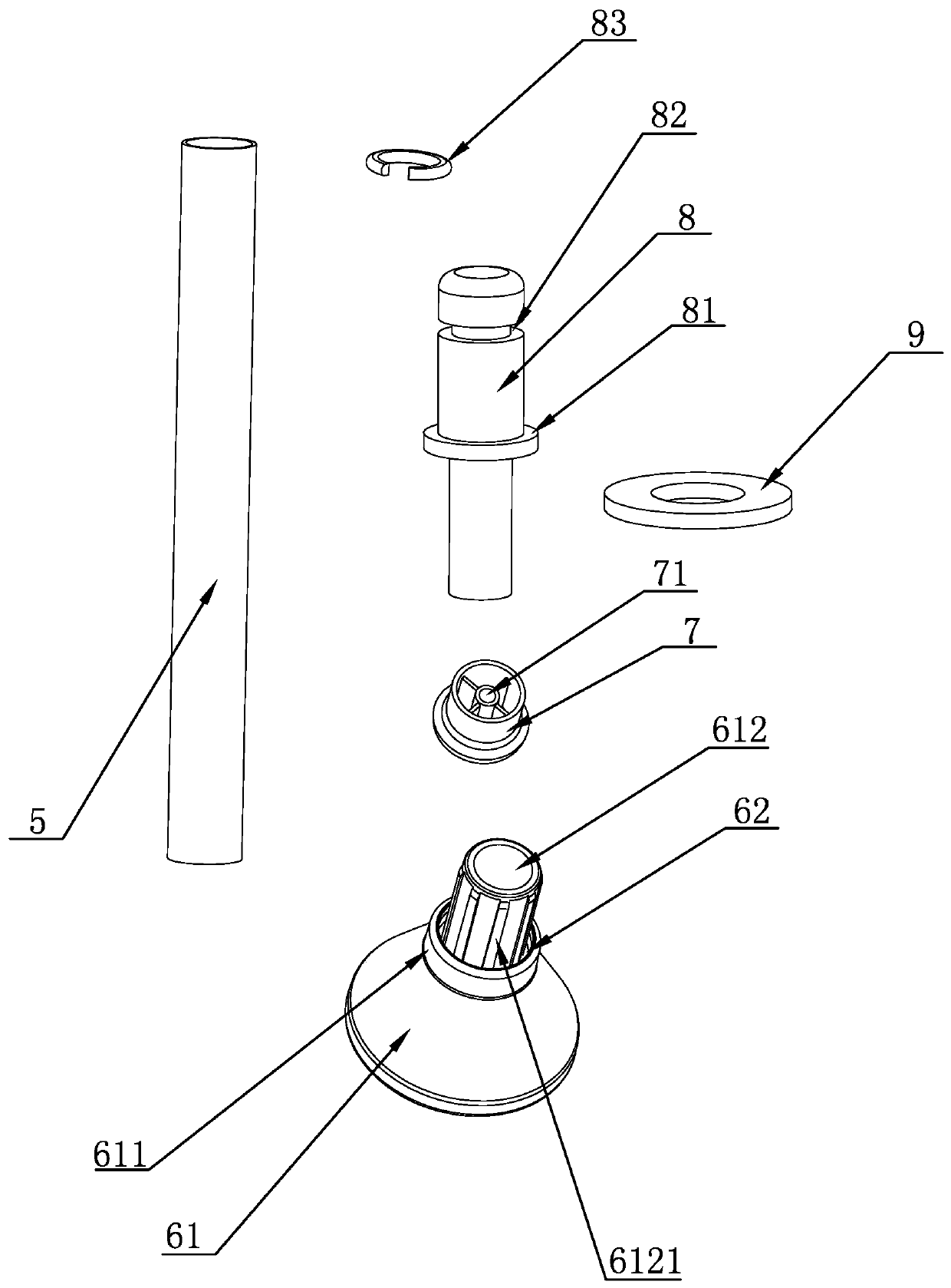
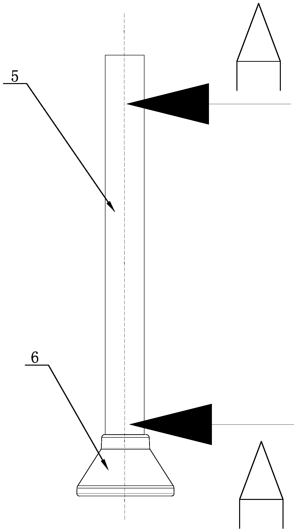
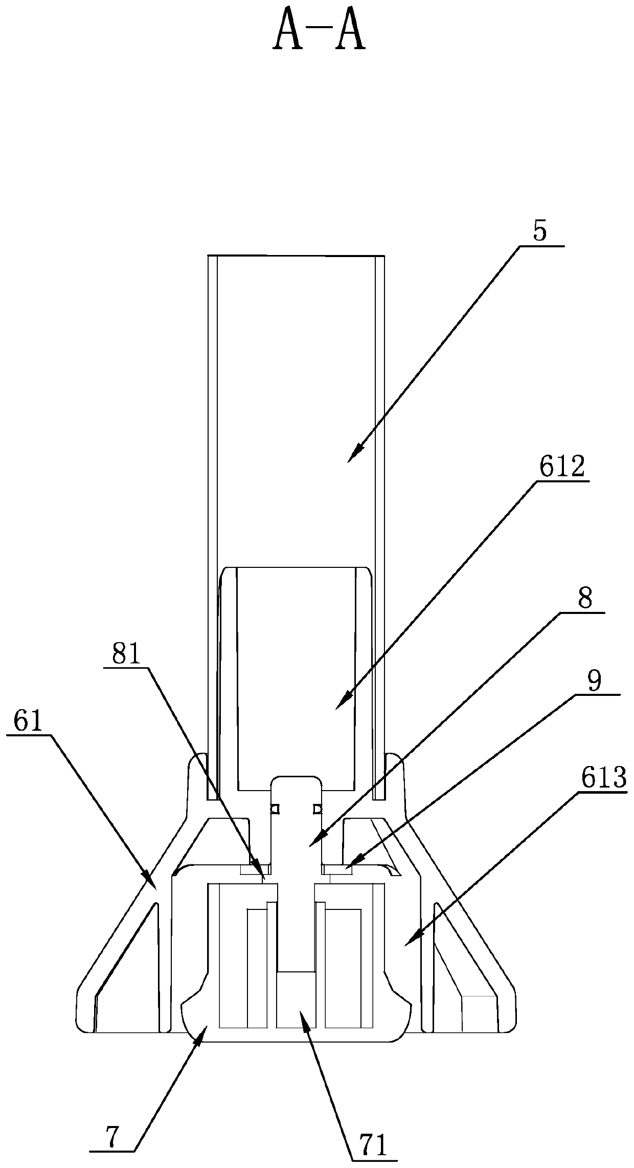
[0025] Such as Figure 1-5 As shown, a rotatable chair foot can be used on a seat that is set as a whole set of tables and chairs, such as Figure 4 The above is the table and chair set in one piece. The supporting table and chair can be used in places such as canteens and conference rooms. The table and chair include a table 1 and a seat 2 connected to the table 1. The seat 2 is connected to the table through a connecting rod 3 On the legs, wherein the seat 2 includes a seat 21 and a support base 4, the support base 4 includes a rotating sleeve 6 and a fixed base 7, the fixed base 7 is arranged on the inner side of the rotating sleeve 6 and is rotatably matched with the rotating sleeve, The bottom surface of the fixed seat 7 is located below the bottom surface of the rotating sleeve 6, the bottom surface of the fixed seat 7 forms a support surface, and the support surface is arranged on the ground in conflict, and of course a support rod can also be provided between the suppo...


PUM


Abstract

The invention relates to a rotatable chair leg. The rotatable chair leg comprises a supporting seat, and is characterized in that the supporting seat comprises a rotating sleeve and a fixed seat; thefixed seat is arranged on the inner side of the rotating sleeve and is in running fit with the rotating sleeve; the bottom surface of the fixed seat is located below the bottom surface of the rotatingsleeve; and the bottom surface of the fixed seat forms a supporting surface. By adopting the technical scheme, the rotatable chair leg can rotate by 360 degrees, so that a user can rotate a chair byany angle to change the orientation of the chair.

Description

technical field [0001] The invention relates to the field of furniture, in particular to a rotatable chair foot. Background technique [0002] There are some desks and chairs whose seats and tables are conjoined in the existing market, such as the desks and chairs adopted in school cafeterias. This one-piece table and chair includes a table and a seat, and the seat is connected to the table through a connecting rod, wherein the seat includes a seat and a supporting base connected with the seat. However, this seat is fixed and cannot be rotated in alignment, so that the seat can only face one direction all the time. Contents of the invention [0003] Purpose of the present invention: In order to overcome the defects of the prior art, the present invention provides a rotatable chair foot, the seat can be rotated 360°, and the user can rotate the seat at any angle to change the position of the seat. towards. [0004] The technical solution of the present invention: a rotat...

Claims


Application Information

Patent Timeline
IPC IPC(8): A47C7/00A47C3/18
CPCA47C7/004A47C3/18
Inventor 苏尚洲汤胜建黄中华
Owner YUCAI HLDG GROUP
Learn More