Pedestrian cooling device of induction escalator

A technology for escalators and cooling devices, applied in escalators, transportation and packaging, etc., can solve the problems of high external temperature, affecting riding comfort, and long descent distance, and achieve high winding density, improved comfort, and high current intensity big effect

Active Publication Date: 2019-12-13
王立强 +2
View PDF9 Cites 0 Cited by
  • Summary
  • Abstract
  • Description
  • Claims
  • Application Information

AI Technical Summary

Problems solved by technology

[0003] However, in the hot summer, although the air conditioner is turned on in the subway station, the distance to the subway station using the escalator at the subway entrance is long and the outside temperature is very high, which greatly affects the comfort of the ride.

Method used


Image

  • Pedestrian cooling device of induction escalator
  • Pedestrian cooling device of induction escalator
  • Pedestrian cooling device of induction escalator

Examples


Embodiment 1

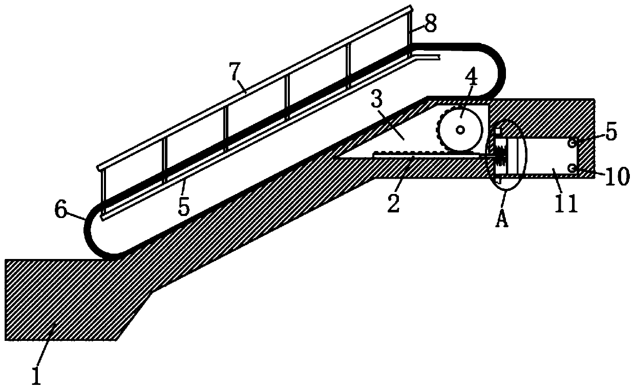
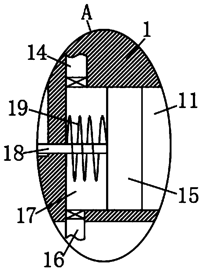
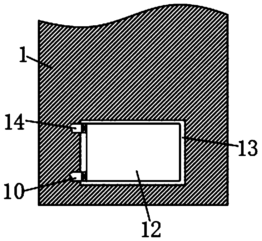
[0023] refer to Figure 1-4 , a pedestrian cooling device for an induction escalator, comprising an elevator base 1 and an escalator body 6, the escalator body 6 can be an inductive elevator, which runs when there are people, and the upper end of the elevator base 1 is provided with The device chamber 3 and the cavity, the output shaft of the drive motor of the escalator body 6 extend into the device chamber 3 and are fixed with an incomplete gear 4, the inner bottom of the device chamber 3 is slidingly connected with the rack 2, and the bottom of the device chamber 3 is provided with There is a slide rail slidingly connected with the rack 2, the rack 2 meshes with the incomplete gear 4, the end of the rack 2 is fixedly connected with a resisting rod 18 extending into the cavity, and one end of the resisting rod 18 located in the cavity is fixed with a Piston 15. Piston 15 is a low temperature resistant piston. Piston 15 divides the cavity into a first cavity 11 and a second c...

Embodiment 2

[0028] refer to Figure 5 The difference between this embodiment and Embodiment 1 is that the piston 15 is embedded with a permanent magnet block 21, the inner wall of the cavity 11 is wrapped with a coil 20, the coil 20 is arranged in a cylindrical shape, and the two ends of the coil 20 are respectively connected with Conductive wires, two conductive wires are connected with the positive and negative poles of the refrigeration cabinet 12 respectively.

[0029] In this embodiment, when the piston 15 moves left and right in the cavity, the permanent magnet block 21 shuttles continuously in the coil 20, thereby generating an induced current, and the generated current is transmitted to the refrigeration cabinet 12 through the conductive wire, because the coil 20 The number of turns is relatively dense, so that the generated current is sufficient to drive the refrigeration cabinet 12 to work without external power supply, which is more energy-saving.


PUM


Abstract

The invention discloses a pedestrian cooling device of an induction escalator. The pedestrian cooling device comprises an elevator pedestal and an escalator body, wherein a device cavity and a cavityare arranged in the upper end of the elevator pedestal; the output shaft of an escalator body drive motor extends into the device cavity and is fixed with an incomplete gear; the bottom in the devicecavity is in sliding connection with a rack; the rack is engaged with the incomplete gear; the tail end of the rack is fixedly connected with an abutting-against rod which extends into the cavity; oneend, in the cavity, of the abutting-against rod is fixed with a piston for dividing the cavity into a first cavity and a second cavity; a spring is arranged on a position, between the piston and theinner wall of the cavity, on the abutting-against rod; a placing slot is formed in one side of the cavity; a refrigerating cabinet is placed in the placing slot; and the first cavity communicates withthe refrigerating cabinet through a first gas sucking tube. The pedestrian cooling device is reasonable in structure, can automatically output cool air while the escalator is used on hot summer days,and greatly improves taking comfort.

Description

technical field [0001] The invention relates to the technical field of escalators, in particular to an induction escalator cooling device for pedestrians. Background technique [0002] With the improvement of living standards, elevators are used more and more frequently. Elevators can be seen everywhere in residential areas, companies and shopping malls. Inductive escalators are also used more and more. When the elevator is stopped, it will automatically start running when someone uses it. At present, the popularity rate of escalators at subway entrances is very high. [0003] However, in the hot summer, although the air conditioner is turned on in the subway station, the distance to the subway station using the escalator at the subway entrance is long and the outside temperature is very high, which greatly affects the ride comfort. Contents of the invention [0004] The purpose of the present invention is to solve the shortcomings in the prior art, and propose an inducti...

Claims


Application Information

Patent Timeline
IPC IPC(8): B66B23/24B66B31/00
CPCB66B23/24B66B31/00
Inventor 陈双文
Owner 王立强
Why Eureka
Try Eureka