A coal-fired coupled biomass power generation system and method

A biomass power generation and biomass pyrolysis technology, which is applied in the direction of combustion method, biofuel, liquid hydrocarbon mixture preparation, etc., can solve the problems of poor adaptability of raw materials, low efficiency of coal-fired coupled biomass power generation, etc.

Active Publication Date: 2021-04-20
HUAZHONG UNIV OF SCI & TECH
View PDF4 Cites 0 Cited by
  • Summary
  • Abstract
  • Description
  • Claims
  • Application Information

AI Technical Summary

Problems solved by technology

[0005] The invention solves the technical problems of low coal-fired coupled biomass power generation efficiency and poor raw material adaptability in the prior art

Method used


Image

  • A coal-fired coupled biomass power generation system and method
  • A coal-fired coupled biomass power generation system and method
  • A coal-fired coupled biomass power generation system and method

Examples


Embodiment 1

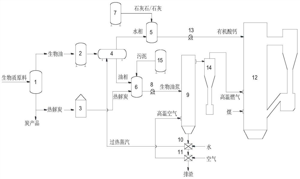
[0056] Such as figure 1 As shown, a coal-fired coupled biomass power generation system and method provided in an embodiment of the present invention includes a biomass pyrolysis unit, a storage and processing unit, a pressurized gasification unit and a coal-fired power generation unit. Among them, the biomass pyrolysis unit 1 is close to a site rich in biomass raw materials, and pyrolyzes the biomass raw materials on-site or nearby to produce bio-oil and pyrolytic charcoal, and a mobile pyrolysis device can also be used. At the same time, part of the pyrolytic charcoal can be processed into high value-added charcoal products, increasing the economic benefits of the pyrolysis unit. Then the bio-oil and pyrolytic charcoal are sent to the oil tank 2 and the charcoal bin 3 of the storage and processing unit of the coal-fired power plant for centralized storage. The oil tank 2 is connected with the oil-water separator 4, and the bio-oil is separated into water phase and oil phase ...

Embodiment 2

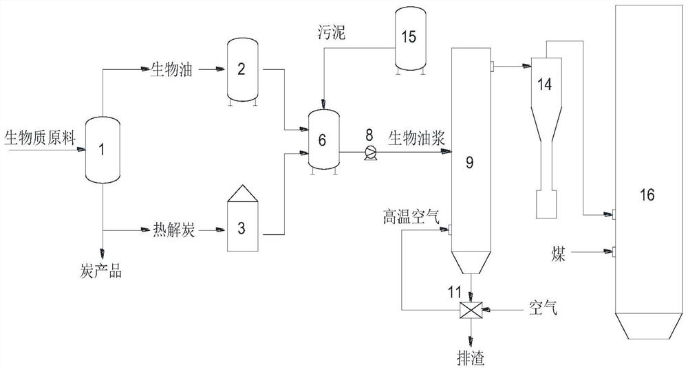
[0058] Such as figure 2 As shown, the operation mode of the biomass pyrolysis unit is consistent with that of Example 1, the difference is the furnace type of the coal-fired boiler, which is a pulverized coal boiler in this example.

[0059] The biomass pyrolysis unit 1 is close to a site rich in biomass raw materials, and pyrolyzes biomass raw materials on-site or nearby to produce bio-oil and pyrolytic charcoal, and a mobile pyrolysis device can also be used. At the same time, part of the pyrolysis charcoal can be processed into high value-added charcoal products, increasing the economic benefits of the pyrolysis unit 1 . Then the bio-oil and pyrolytic charcoal are sent to the oil tank 2 and the charcoal bin 3 of the storage and processing unit of the coal-fired power plant for centralized storage. The bio-oil and pyrolytic carbon are prepared in the bio-oil slurry mixing tank 6, and the pyrolytic carbon and bio-oil are mixed at a mass ratio of 1: (2-10), and the particle ...

Embodiment 3

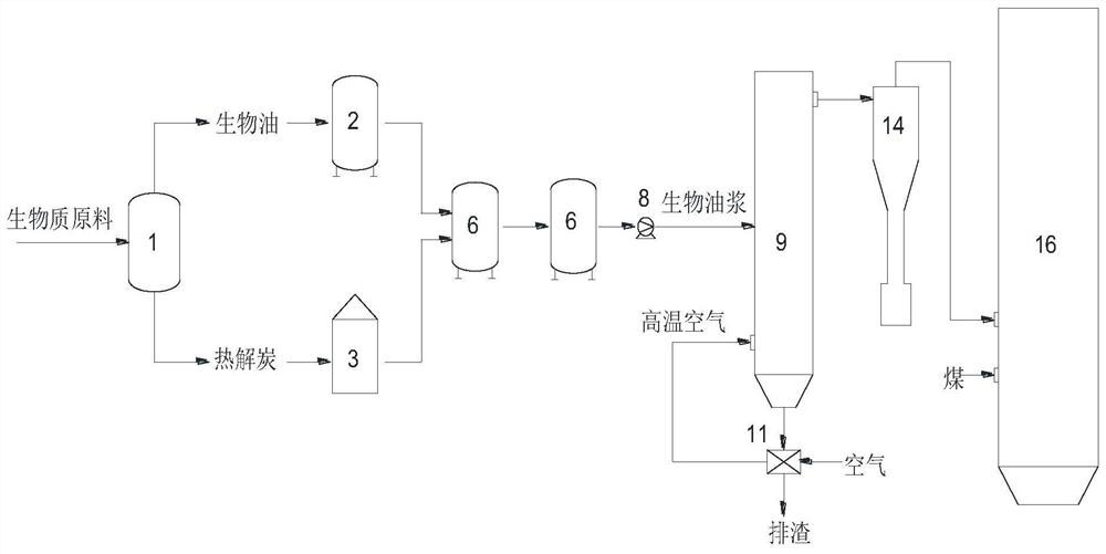
[0061] Such as image 3 As shown, a coal-fired coupled biomass power generation system and method provided in an embodiment of the present invention includes a biomass pyrolysis unit, a storage and processing unit, a pressurized gasification unit and a coal-fired power generation unit. Among them, the biomass pyrolysis unit 1 is close to a site rich in biomass raw materials, and pyrolyzes the biomass raw materials on-site or nearby to produce bio-oil and pyrolytic charcoal, and a mobile pyrolysis device can also be used. The bio-oil and pyrolytic carbon are stored in the oil tank 2 and the carbon bin 3 respectively, and the two are prepared in the bio-oil slurry tank 6, and the pyrolytic carbon and the bio-oil are mixed in a mass ratio of 1: (2-10) , Pyrolytic carbon particle size is less than 1mm. Then the bio-oil slurry is sent to the bio-oil slurry tank 6 arranged in the coal-fired power plant for centralized storage, and then sent to the pressurized gasifier 9 under the a...


PUM

PropertyMeasurementUnit
particle diameteraaaaaaaaaa

Abstract

The invention relates to a coal-fired coupled biomass power generation system and method, belonging to the technical field of biomass energy. The system includes biomass pyrolysis unit, storage processing unit, pressurized gasification unit and coal-fired power generation unit. First, the biomass raw material is converted into bio-oil and pyrolytic carbon by pyrolysis nearby, and then processed into bio-oil slurry and calcium organic acid; the bio-oil slurry uses a pressurized gasifier to produce high-temperature gas, and directly sends it to a coal-fired boiler for co-combustion generate electricity. The invention realizes the efficient conversion and utilization of waste resources such as biomass and sludge, and can meet the large-scale coal-fired power plant coupled with biomass power generation scale requirements, and at the same time co-produce high value-added carbon products, organic acid calcium can also be used for The desulfurization and denitrification in the circulating fluidized bed boiler has a good application prospect.

Description

technical field [0001] The invention belongs to the technical field of biomass energy, and more specifically relates to a coal-fired coupled biomass power generation system and method. Background technique [0002] In recent years, with the continuous development of my country's economy, the demand for electricity has continued to grow. More than 70% of my country's electricity is still supplied by coal-fired power plants. Large-scale coal combustion will inevitably bring many environmental problems. Increasing the proportion of power generation using clean and renewable energy is an important topic in today's green development environment, and it is also the only way to achieve sustainable development. Biomass energy, as the only renewable carbon source, has many advantages such as abundant raw materials, low price and easy availability, low-carbon environmental protection, and sustainable regeneration. According to calculations, the biomass resources that can be used as ...

Claims


Application Information

Patent Timeline
Patent Type & Authority Patents(China)
IPC IPC(8): C10B53/02C10G1/00C10G33/00F23C10/22
CPCC10B53/02C10G1/00C10G33/00F23C10/22Y02E50/10
Inventor 杨海平李思芹谢迎谱王贤华胡俊豪邵敬爱杨晴陈应泉张雄张世红陈汉平
Owner HUAZHONG UNIV OF SCI & TECH
Why Eureka
Try Eureka