
A bearing ring grabbing chuck

A technology for grabbing chucks and bearing rings, applied to chucks, manufacturing tools, manipulators, etc., can solve the problem of no protection for permanent magnets, and achieve the effect of reducing damage

Active Publication Date: 2021-03-26
玉环市星光眼镜厂
View PDF6 Cites 0 Cited by
  • Summary
  • Abstract
  • Description
  • Claims
  • Application Information

AI Technical Summary

Problems solved by technology

[0004] The object of the present invention aims at the technical problem that the permanent magnet of the existing bearing ring chuck is not protected, and provides a bearing ring grabbing chuck

Method used


Image

  • A bearing ring grabbing chuck
  • A bearing ring grabbing chuck

Examples


specific Embodiment approach

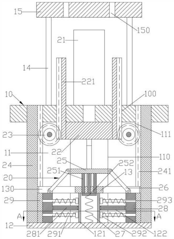
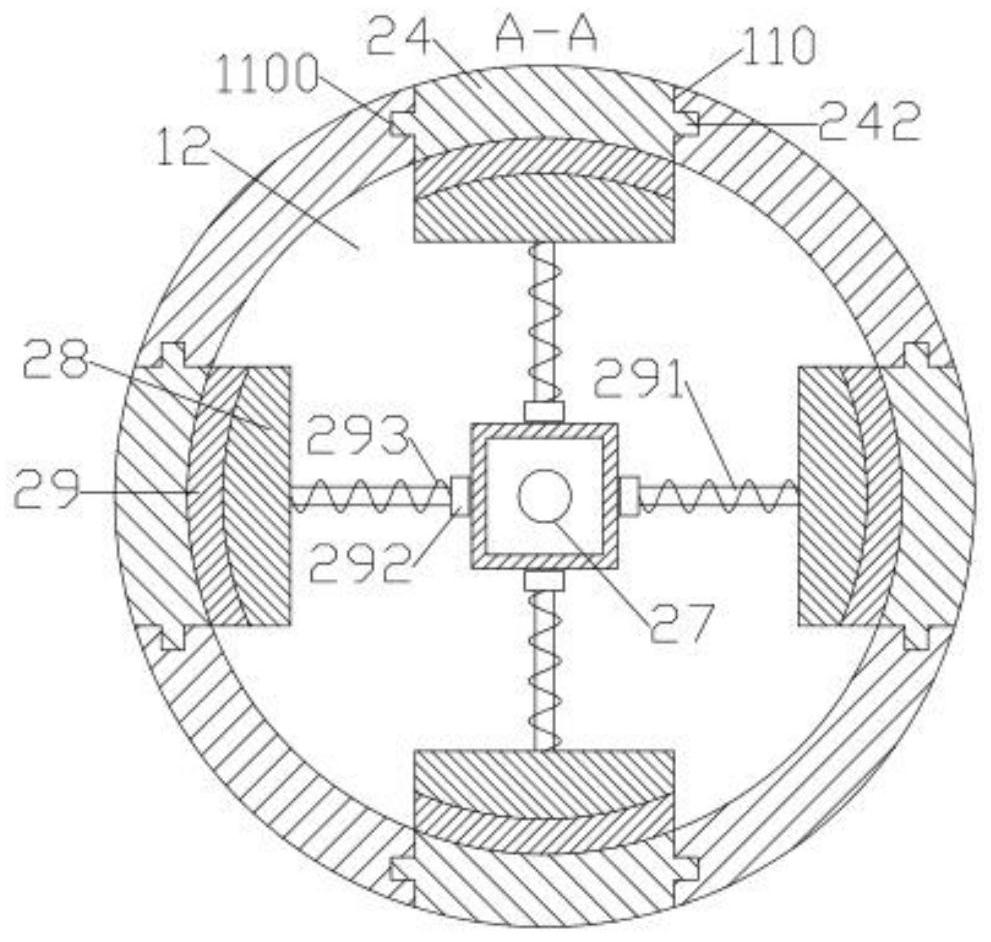
[0014] Specific implementation methods such as figure 1 , figure 2 As shown, a bearing ring grab chuck includes a circular plate-shaped central support plate 10; the lower end surface of the central support plate 10 is formed with a lower support cylinder 11 coaxially provided with a circular cylindrical shape; The bottom of the support tube 11 is formed with a lower support plate 12; the side wall of the lower support tube 11 is formed with a number of evenly distributed radially extending rectangular hole-shaped vertical telescopic slots 110; the upper end of the vertical telescopic slot 110 penetrates upwards Central support plate 10; the center of the upper end surface of the central support plate 10 is fixed with a lift cylinder 21; the piston rod of the lift cylinder 21 penetrates the center support plate 10 downwards and is fixed with a circular plate-shaped lift support plate 22; a vertical telescopic groove 110 The inner lift is provided with a guard plate 24 made o...


PUM


Abstract

The invention discloses a grabbing chuck for a bearing ring. The grabbing chuck for the bearing ring further comprises a linkage device; a protective plate composed of a non-magnetic material is arranged in a vertical telescopic groove in a lifted mode; a plurality of movable supporting plates which are uniformly and circumferentially distributed and are composed of non-magnetic materials are elastically and radially movably arranged on the upper end surface of a lower supporting plate; arc-shaped permanent magnets are elastically and radially movably arranged at the outer side end of the movable supporting plates; the lower part of the vertical telescopic groove allows the movable supporting plate and the permanent magnets on the movable supporting plate to radially penetrate through; andthe linkage device comprises an upper linkage device body and a lower linkage device body. According to the grabbing chuck for the bearing ring, through the upper linkage device body, a lifting supporting plate ascends and descends to drive the protective plate to ascend and descend, and the lifting supporting plate and the protective plate are reversely movably arranged; through the lower linkage device body, the lifting supporting plate descends to drive the movable supporting plates to radially move away; and in the descending process of the lifting supporting plate, when the movable supporting plates start to move radially, the protective plate is positioned on the upper sides of the movable supporting plates and the permanent magnets. The grabbing chuck for the bearing ring has the advantages that the permanent magnets can be prevented from accidentally adsorbing metal particles, and the damage to an inner ring body of the bearing ring in the grabbing process is reduced.

Description

technical field [0001] The invention relates to the technical field of bearing production, in particular to a gripper for a bearing ring. Background technique [0002] Bearings are components that fix and reduce the friction coefficient of loads in the process of mechanical transmission, and are an important part of contemporary mechanical equipment. The existing bearing manufacturing production is gradually changing from manual to fully automated. Robots and manipulators play a vital role in the fully automated production of bearings. Gripper, although its mechanical jaw has good versatility, it is inconvenient to clamp the inner or outer ring of the ring. There are only two points of contact between the jaw and the inner or outer ring. The clamping force is small and the friction It is not enough to lift the bearing ring, and when the clamping force is large, it is easy to affect the quality of the inner or outer wall of the bearing ring; [0003] The invention patent ap...

Claims


Application Information

Patent Timeline
Patent Type & Authority Patents(China)
IPC IPC(8): B25J15/06
CPCB25J15/0608
Inventor 蔡盼
Owner 玉环市星光眼镜厂
Learn More