

Built-in traction mechanism
A traction mechanism, built-in technology, applied in the field of machinery, can solve the problems of traction mechanism and mold interference, not conforming to the actual use process, large structural size, etc., to achieve the effect of small mechanism size, convenient operation and stable movement
- Summary
- Abstract
- Description
- Claims
- Application Information
AI Technical Summary
Problems solved by technology
Method used
Image

Examples
Embodiment Construction
[0014] The present invention will be further described below in conjunction with the accompanying drawings and embodiments.
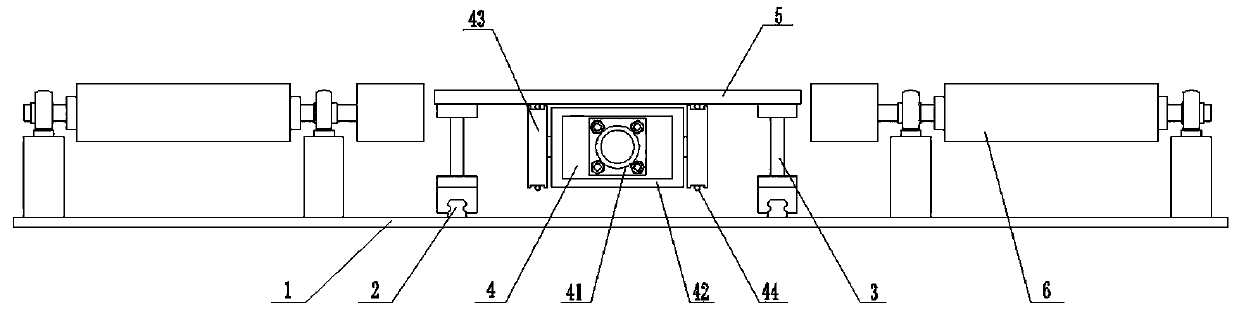
[0015] Such as figure 1 As shown, a built-in traction mechanism according to the present invention includes a base plate 1, a sliding guide rail 2, and a traction power mechanism 4; the sliding guide rail 2 is installed on the base plate 1, and a support column 3 is installed on the sliding guide rail 2 , the mold moving pallet 5 is connected and supported by the support column 3 to slide on the sliding guide rail 2, the lower part of the mold moving pallet 5 is connected to the traction power mechanism 4, and the traction mechanism is integrally installed between the two rows of mold guide wheels 6 on the bottom plate 1 .
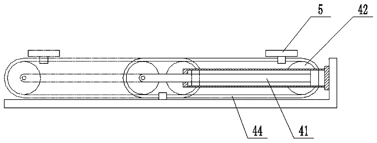
[0016] Described driving force mechanism 4 comprises hydraulic cylinder 41, roller frame 42, and hydraulic cylinder 41 is installed in the roller frame 42, and the piston rod in the hydraulic cylinder 41 is connected with roller fr...
PUM
 Abstract
Description
Claims
Application Information