Vehicle software state monitoring and pre-warning system

A state monitoring and early warning system technology, applied to vehicle parts, body, body stability, etc., can solve problems such as uneven road surface, large road surface undulations, difficult vehicle state judgment, etc., to reduce the risk of overturning and improve safety.

Inactive Publication Date: 2019-12-20
李莎
View PDF0 Cites 0 Cited by
  • Summary
  • Abstract
  • Description
  • Claims
  • Application Information

AI Technical Summary

Problems solved by technology

[0002] When the vehicle is running, especially when driving off-road, the road surface often has large ups and downs. Professional racers can easily cause the vehicle to overturn when they are not familiar with it. However, many domestic country roads are uneven due to disrepair. It is difficult for the staff to judge the state of the vehicle, and they cannot intuitively understand the current driving state of the vehicle. Currently, only a series of equipment such as shock absorbers are installed on the vehicle for shock absorption and shock absorption, and there is no real-time monitoring and early warning of the vehicle state. The system can let the driver understand the status of the vehicle, and according to the emergency, by changing the balance, the vehicle will not easily turn over, ensuring the safety of the people in the vehicle

Method used


Image

  • Vehicle software state monitoring and pre-warning system
  • Vehicle software state monitoring and pre-warning system
  • Vehicle software state monitoring and pre-warning system

Examples


Embodiment 2

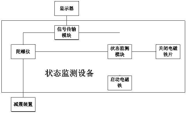
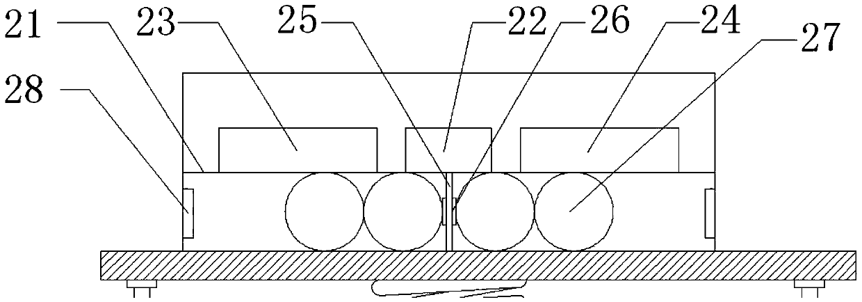
[0022] Such as figure 2 As shown, the difference between this embodiment and the first embodiment is that the state monitoring device 2 is provided with a partition plate 21 to divide the state monitoring device into upper and lower layers. A gyroscope 22 is arranged in the middle of the upper layer of the state monitoring device 2 , and a signal transmission module 23 and a state monitoring module 24 are respectively arranged on both sides of the gyroscope 22 . The middle part of the lower layer of the condition monitoring device 2 is provided with a baffle plate 25, the upper end of the baffle plate 25 is connected with the lower end surface of the partition plate 21, and the lower end of the baffle plate 25 is connected with the upper end surface of the installation platform 1; the left and right sides of the baffle plate 25 The end face is provided with a fixed electromagnet 26, the fixed electromagnet 26 sucks the balance ball 27, and the fixed electromagnet 26 is equipp...

Embodiment 3

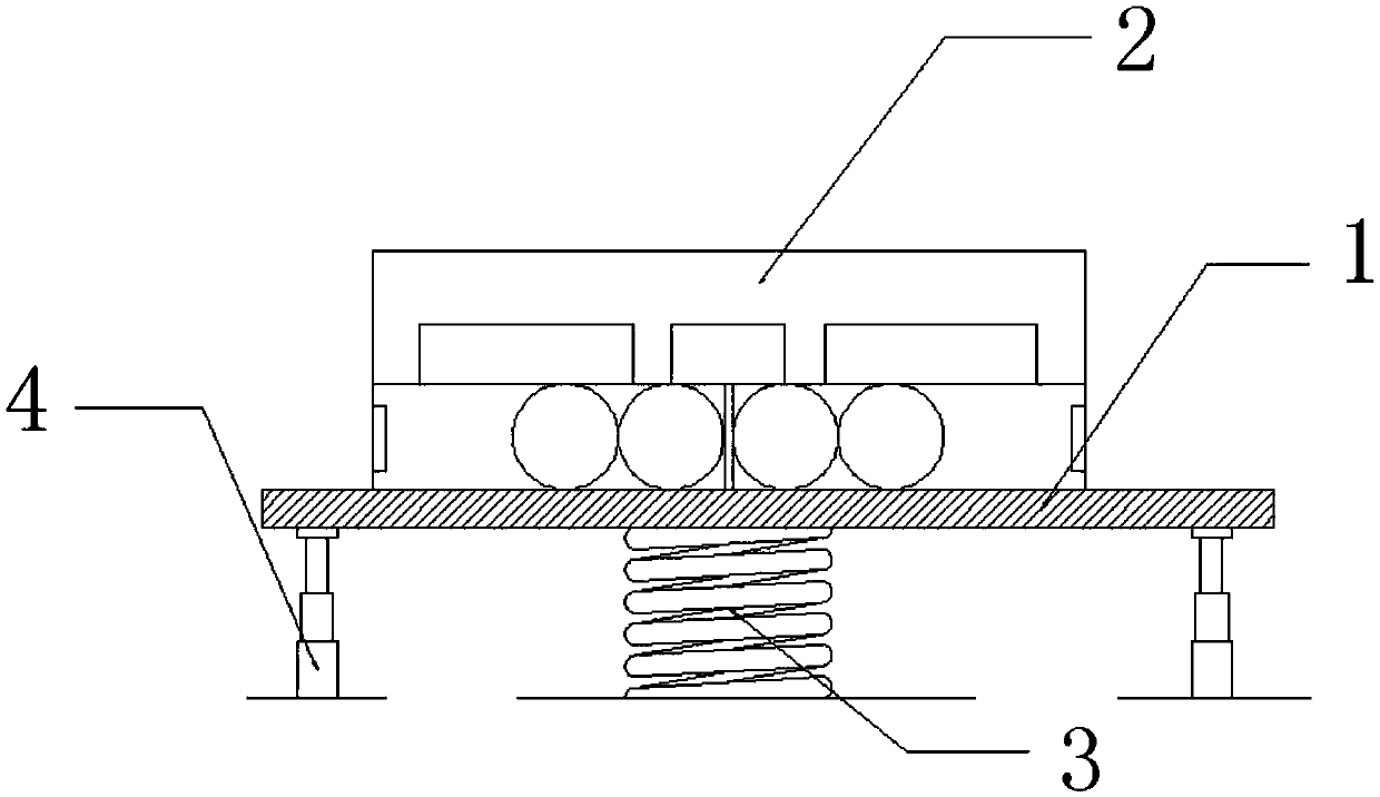
[0024] Such as image 3 As shown, the only difference between this embodiment and Embodiment 1 is that the damping device 4 includes a hydraulic cylinder 41, a hydraulic rod 42, and a fixed plate 43. The rod chamber of the hydraulic cylinder 41 is connected to one end of the hydraulic rod 42, and the hydraulic pressure The other end of the rod 42 is connected to the fixed plate 43 ; the fixed plate 43 is connected to the installation platform 1 .


PUM


Abstract

The invention discloses a vehicle software state monitoring and pre-warning system. According to the vehicle software state monitoring and pre-warning system, state monitoring equipment is mounted ona mounting platform; a shock absorbing spring is arranged at the middle part of the lower end surface of the mounting platform; shock absorbing devices are mounted on the left and right sides of the lower end surface of the mounting platform; the shock absorbing springs are arranged on a vehicle body; the shock absorbing devices are arranged on a vehicle suspension; and when a vehicle suffers fromshock, the suspension transmits the shock to the shock absorbing devices, the shock absorbing devices drive the mounting platform to move up and down, the state monitoring equipment monitors the displacement amount, and a signal is transmitted into a vehicle display in real time. A driver judges a state of the vehicle through display information in the display to perform operation, and therefore,turnover of the vehicle can be avoided; and the state monitoring equipment judges possible inclination angles of different vehicles according to different designs of the vehicles after vehicle information is recorded and performs pre-warning in advance before the angles are reached.

Description

technical field [0001] The invention relates to a monitoring and early warning system, in particular to a vehicle software state monitoring and early warning system. Background technique [0002] When the vehicle is running, especially when driving off-road, the road surface often has large ups and downs. Professional racers can easily cause the vehicle to overturn when they are not familiar with it. However, many domestic country roads are uneven due to disrepair. It is difficult for the staff to judge the state of the vehicle, and they cannot intuitively understand the current driving state of the vehicle. Currently, only a series of equipment such as shock absorbers are installed on the vehicle for shock absorption and shock absorption, and there is no real-time monitoring and early warning of the vehicle state. The system can let the driver understand the status of the vehicle, and according to the emergency, by changing the balance, the vehicle will not easily turn over...

Claims


Application Information

Patent Timeline
Patent Type & Authority Applications(China)
IPC IPC(8): B60R16/02B60R1/00B62D37/04G01C9/00
CPCB60R1/00B60R16/02B62D37/04G01C9/00
Inventor 李莎
Owner 李莎
Why Eureka
Try Eureka