An I-shaped wheel automatic wire withdrawal mechanism

A technology of I-shaped wheel and driving mechanism, which is applied in the direction of conveying filamentous materials, thin material handling, transportation and packaging, etc., can solve the problems that the wire coil is prone to random wires, non-layer winding, waste of materials and personnel, etc. To achieve the effect of reducing labor and material waste, avoiding stacking and messy wires, and simple connection methods

Active Publication Date: 2020-12-01
长沙衡开智能科技有限公司
View PDF14 Cites 0 Cited by
  • Summary
  • Abstract
  • Description
  • Claims
  • Application Information

AI Technical Summary

Problems solved by technology

[0004] As the application of automatic welding becomes more and more extensive, the demand for welding wire is also increasing. During the working process of the layer winding machine, due to the inconsistent synchronization of various mechanisms or manual installation errors, etc., disordered wires are prone to appear on the welding wire reel. That is to say, the welding wire on the welding wire reel is in a non-layer winding and irregular stacking state. During the operation of the existing layer winding machine, when there is disordered wire on the welding wire reel, it is manually operated to withdraw the wire, so that the welding wire reel and the I-shaped The wheel is reversed to make the messy wire on the wire reel wind back to the I-shaped wheel. Since the moving speed of the wire pressing mechanism and straightening mechanism of the layer winding machine is set to match the rotation of the wire reel, the wire will be unwound in the reverse rotation. During the process, the wire pressing mechanism and straightening mechanism of the original layer winding machine will not keep matching with the rotation of the I-shaped wheel. Therefore, the welding wire wound back on the I-shaped wheel will be stacked at the same position, resulting in disordered wires.
Once the messy wire appears again on the I-shaped wheel, the welding performance of the welding wire will be affected by the bending or scars caused by the irregular stacking of the part of the welding wire that has the messy wire, and it can no longer be used, so this part has the secondary messy wire The welding wire can only be removed, which wastes materials and personnel and increases the cost. Therefore, there is an urgent need to design and produce an I-wheel automatic wire-removing and arranging mechanism in the prior art to solve this problem

Method used


Image

  • An I-shaped wheel automatic wire withdrawal mechanism
  • An I-shaped wheel automatic wire withdrawal mechanism
  • An I-shaped wheel automatic wire withdrawal mechanism

Examples


Embodiment Construction

[0026] The embodiments of the present invention will be described in detail below with reference to the accompanying drawings, but the present invention can be implemented in various ways defined and covered by the claims.

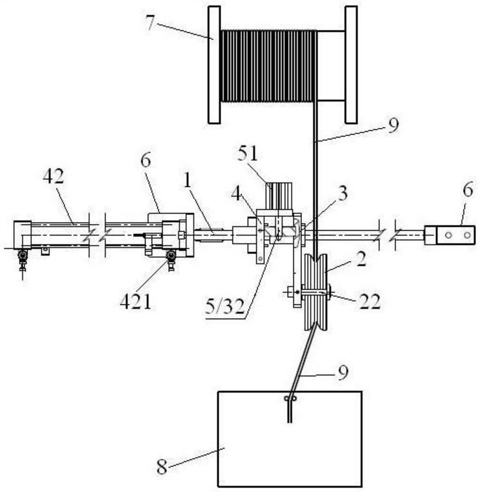
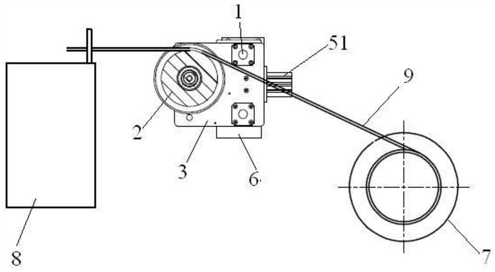
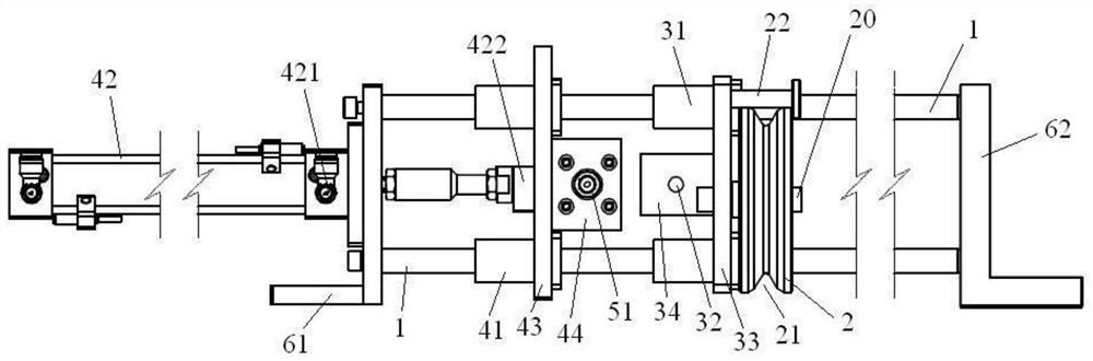
[0027] see Figure 1 ~ Figure 4 A kind of I-shaped wheel automatic thread withdrawal mechanism, including guide rod 1, wire arrangement guide wheel 2, wire arrangement frame 3, linkage frame 4 and linkage pin 5, the guide rod is arranged on the bracket 6, and the guide rod is located on the Between the I-shaped wheel 7 and the layer winding machine 8, and the length direction of the guide rod is set in a direction parallel to the axial direction of the I-shaped wheel. The wire arrangement guide wheel is rotatably arranged on the cable rack 3 through the support rod 20, and the support rod As the center of rotation of the wire-arraying guide wheel, the axial direction of the wire-arranging guide wheel is parallel to the axial direction of the I-shaped wheel...


PUM


Abstract

The invention provides an automatic wire withdrawing and arranging mechanism for an inverted-H-shaped wheel. The automatic wire withdrawing and arranging mechanism comprises a guide rod, a wire arranging guide wheel, a wire arranging frame, a linking frame and a linking pin arranged on the linking frame, wherein the linking frame is connected with a drive mechanism I which is matched with the inverted-H-shaped wheel in speed; the linking pin is connected with a drive mechanism II; the linking pin can be driven by the drive mechanism I to slide back and forth in a direction parallel to a lengthdirection of the guide rod along with the linking frame; a connecting pin hole is formed in the wire arranging frame; the linking pin can extend out of and can be inserted into the connecting pin hole to realize connection between the drive mechanism I and the wire arranging guide wheel, so that the wire arranging guide wheel obtains moving speed matched with the inverted-H-shaped wheel, and therefore, wire arranging effect is provided for the inverted-H-shaped wheel, and welding wires re-wound on the inverted-H-shaped wheel are orderly arranged to avoid stacking and wire-disordering phenomena, waste of labor and materials is reduced, and production cost is reduced. When the linking pin is withdrawn and separated from the wire arranging guide wheel, the wire arranging guide wheel can perform normal wire arranging work on a welding wire disc, so that the automatic wire withdrawing and arranging mechanism is flexible and convenient, and is high in operability.

Description

technical field [0001] The invention relates to welding wire layer winding equipment, in particular to an I-shaped wheel automatic wire-rewinding and arranging mechanism. Background technique [0002] Welding wire is a welding material used as a filler metal or as a conductive wire at the same time, including carbon steel welding wire, low alloy structural steel welding wire, alloy structural steel welding wire, stainless steel welding wire and non-ferrous metal welding wire. The surface of the welding wire is not coated with anti-oxidation flux, and it is used as filler metal in gas welding and gas tungsten arc welding; it is both filler metal and Conductive electrodes. [0003] After the welding wire is produced, it is wound on the I-shaped pay-off reel in a non-layer winding manner (in this application, "I-shaped pay-off reel" is referred to as "I-shaped reel" for short), and then passed through the layer winding machine. (such as a welding wire layer winding machine di...

Claims


Application Information

Patent Timeline
Patent Type & Authority Patents(China)
IPC IPC(8): B65H54/00B65H54/70
CPCB65H54/00B65H54/70
Inventor 邹湘衡洪新东刘欲来
Owner 长沙衡开智能科技有限公司
Why Eureka
Try Eureka