
Piston type valve element structure combining rigid ring surface with flexible base surface and method thereof

A technology of piston valve and rigid ring, which is applied to the device for pressure relief on the sealing surface, lift valve, valve details, etc., can solve the problem of unbalanced force on the piston valve core, and achieve the guarantee of sealing performance, Easy to manufacture and simple in structure

Active Publication Date: 2019-12-20
ZHEJIANG UNIV
View PDF4 Cites 2 Cited by
  • Summary
  • Abstract
  • Description
  • Claims
  • Application Information

AI Technical Summary

Problems solved by technology

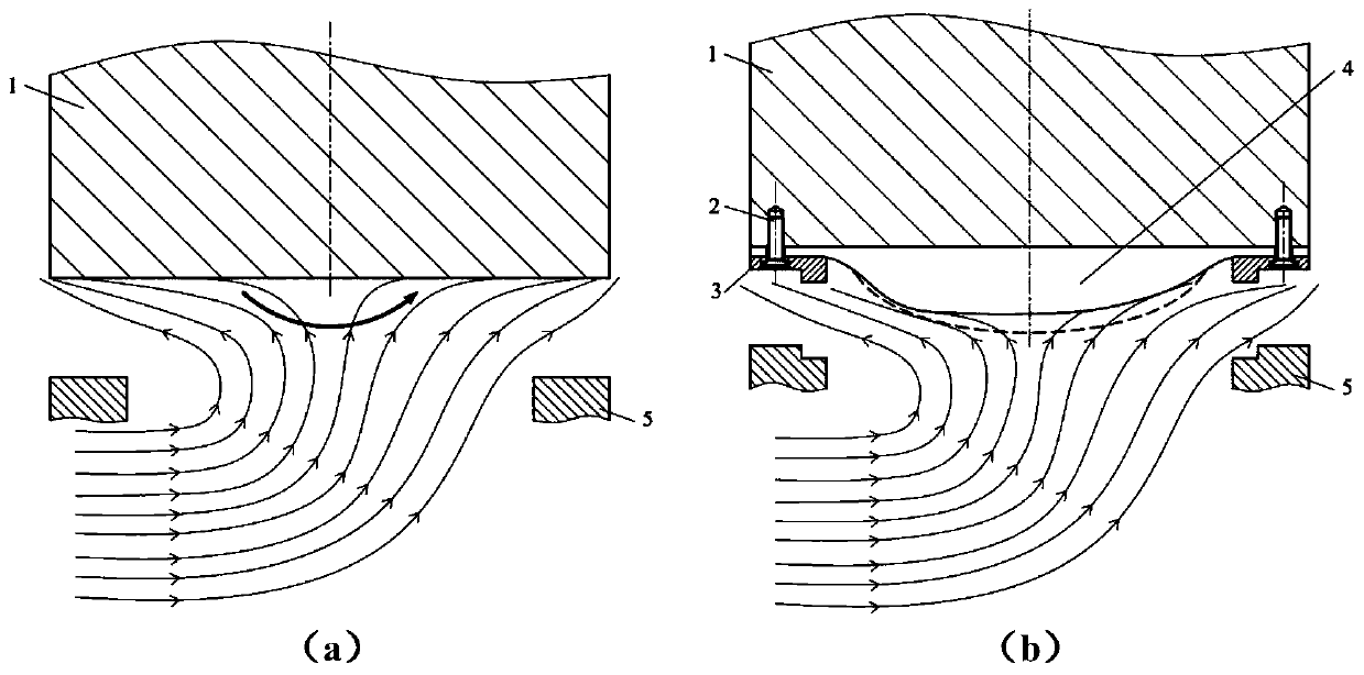
[0004] The purpose of the present invention is to solve the phenomenon of unbalanced force on the existing piston-type valve core, and provide a piston-type valve core structure with a rigid ring surface combined with a flexible base surface

Method used


Image

  • Piston type valve element structure combining rigid ring surface with flexible base surface and method thereof
  • Piston type valve element structure combining rigid ring surface with flexible base surface and method thereof
  • Piston type valve element structure combining rigid ring surface with flexible base surface and method thereof

Examples


Embodiment Construction

[0024] The present invention will be further described below in conjunction with the accompanying drawings.

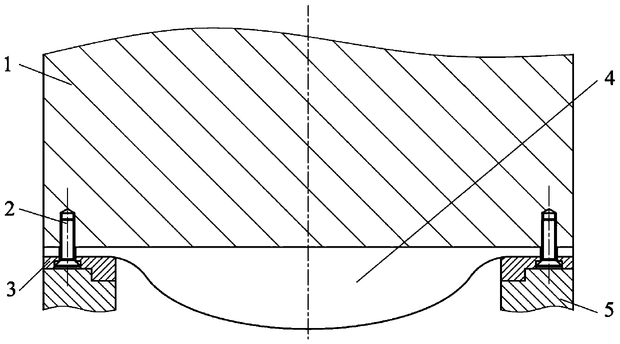
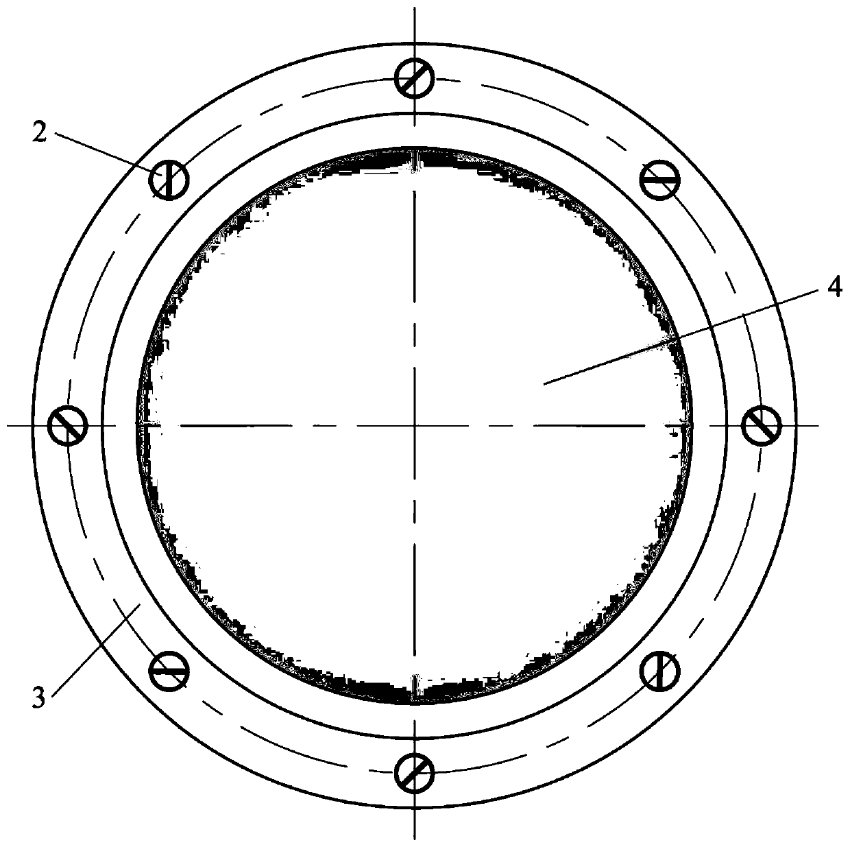
[0025] like figure 1 , figure 2 Shown is a piston-type spool structure with a rigid annular surface combined with a flexible base surface in a preferred embodiment of the present invention, and the piston-type spool structure is used to be installed above the valve seat 5 . Its main structure includes a connecting piece 2 and a piston valve core 1 , a flexible base surface 4 and a rigid ring surface 3 which are stacked and assembled sequentially from top to bottom.

[0026] Wherein, the piston type spool 1 is in the form of a cylinder with a flat bottom surface. The flexible base surface 4 is an irregular convex surface with thin edges and thick middle. The edge is used as a fixed part. The flexible base surface 4 is made of flexible material, which can deform when the bottom surface is subjected to external force. In this embodiment, the material of the flexible...


PUM


Abstract

The invention discloses a piston type valve element structure combining a rigid ring surface with a flexible base surface and a method thereof. The valve element structure comprises a piston type valve element, the flexible base surface, the rigid ring surface and a connecting piece which are sequentially stacked and assembled from top to bottom; the bottom surface of the piston type valve elementis a flat surface; the flexible base surface is thin in edge and thick in middle, the top surface of the flexible base surface attaches to the bottom surface of the piston type valve element, and thebottom surface is an ellipsoidal convex surface; the flexible base surface is made of a flexible material, and deformation can occur when the bottom surface is subjected to external force; the rigidring surface is a ring body with a cross section in a stepped shape, and the bottom surface of the rigid ring surface serves as a contact surface between the valve element structure and a valve seat;the rigid ring surface is coaxially arranged on the edge of the bottom surface of the flexible base surface, the bottom surface of the piston type valve element is taken as a baseline, and the centralprotrusion height of the ellipsoidal convex surface of the flexible base surface is greater than the protrusion height of the rigid ring surface; and the connecting piece is used for connecting the structures so that the structures are assembled into a whole. The piston type valve element structure combining the rigid ring surface with the flexible base surface can be used for overcoming the unbalanced torque on the bottom surface of the valve element, and is simple in structure and can be widely popularized and applied.

Description

technical field [0001] The invention relates to a piston type valve core structure, in particular to a piston type valve core structure with a rigid ring surface combined with a flexible base surface and a method for overcoming unbalanced moment. Background technique [0002] In a horizontally arranged valve with a piston-type spool structure, the force on the bottom surface of the spool shows an obvious unbalanced phenomenon, and the pressure on the lower surface of the spool bottom near the fluid outlet side is greater than that near the fluid inlet side. , the unbalanced pressure distribution causes an unbalanced moment on the bottom surface of the valve core, and causes the wall of the valve core to be squeezed against the sealing part, which not only increases the driving energy consumption, affects the sealing performance, and even causes the valve to leak under the condition of large flow invalidated. [0003] In the current piston valve structure on the market, ther...

Claims


Application Information

Patent Timeline
Patent Type & Authority Applications(China)
IPC IPC(8): F16K1/36
CPCF16K1/36F16K39/022F16K1/46F16K1/54
Inventor 钱锦远母娟侯聪伟金志江
Owner ZHEJIANG UNIV
Learn More