A High Rigidity Crank Slider Optical Mirror Group Switching Mechanism

A technology of crank slider and switching mechanism, which is applied in the field of optical instruments, can solve problems such as poor support stiffness, achieve the effects of improving stability, improving support stiffness and locking effect, and reducing locking force

Active Publication Date: 2020-01-14
LUOYANG INST OF ELECTRO OPTICAL EQUIP OF AVIC
View PDF7 Cites 0 Cited by
  • Summary
  • Abstract
  • Description
  • Claims
  • Application Information

AI Technical Summary

Problems solved by technology

[0006] In order to avoid the deficiencies of the prior art, the present invention proposes a high-rigidity crank-slider optical mirror group switching mechanism. Aiming at the problem of poor support rigidity of the traditional rotary switching mechanism, based on the crank-slider configuration, a simple Reliable, high-rigidity switching mechanism for the optical mirror group. By adding a set of supporting connecting rods, the support rigidity of the switching mirror group is greatly improved. At the same time, the locking performance of the switching mirror group is improved through the design of the angle of the crank slider mechanism.

Method used


Image

  • A High Rigidity Crank Slider Optical Mirror Group Switching Mechanism
  • A High Rigidity Crank Slider Optical Mirror Group Switching Mechanism
  • A High Rigidity Crank Slider Optical Mirror Group Switching Mechanism

Examples


specific Embodiment

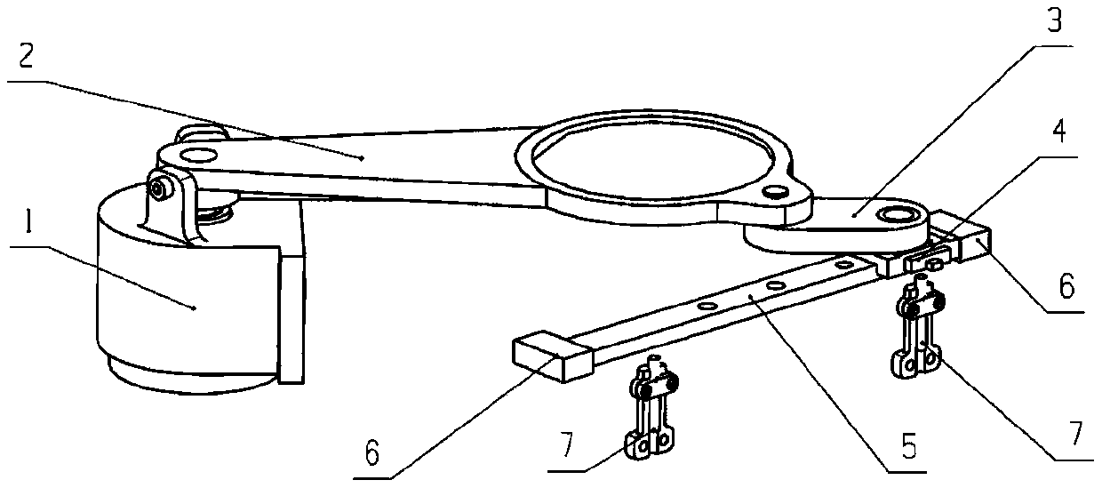
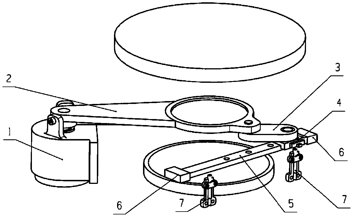
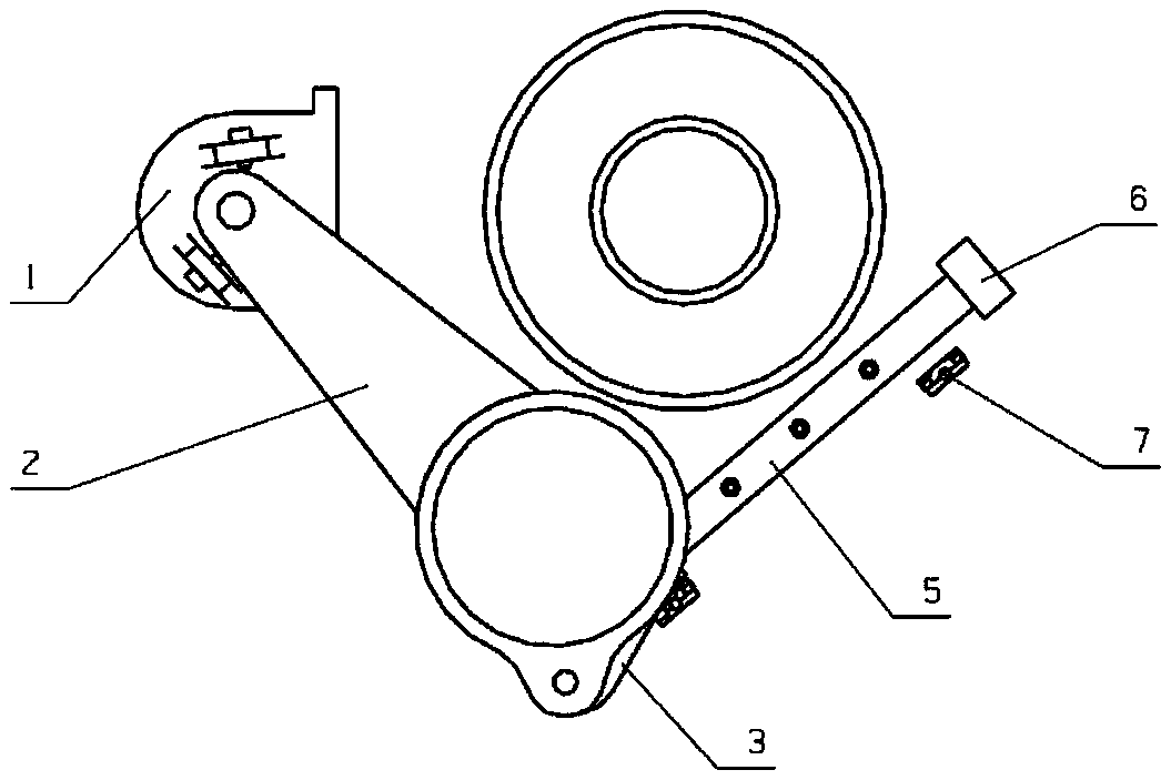
[0043] Such as figure 1 , figure 2 and image 3 As shown, the rotary drive device 1, the linear guide rail 5 and the proximity sensor 7 need to be independently installed on the outer casing of the equipment, and their mutual positions may need to be adjusted during assembly.

[0044] Such as Figure 4 As shown, the rotary driving device 1 is composed of a motor housing 11 , a motor 12 , an adapter bush 13 , a drive shaft 14 , a bearing bush 15 , a bearing 16 and a limit screw 17 . The motor housing 11 is the main structural part of the entire rotary drive device 1 , the stator of the motor 12 is fixed on the motor housing 11 , and the two are generally threaded. The rotor of the motor 12 is coupled with the drive shaft 14 through an adapter bush 13 . When the torque is small, the drive shaft 14 and the adapter bushing 13 can be used for interference fit, and when the torque is large, it is necessary to increase the flat key to transmit the torque. The adapter bushing 13...


PUM


Abstract

The invention relates to a high-rigidity crank slider optical mirror group switching mechanism, which is used to realize the radial rotation cut-in and cut-out functions of a certain mirror group in an optical system. The switching mirror group is driven to rotate by the rotating drive device, so as to realize the cut-in and cut-out of the switching mirror group in the optical path; the switching mirror group is connected with the slider and the linear guide rail through the supporting link to provide auxiliary support, which improves the switching under dynamic conditions. The stability of the mirror group; through the design of the angle of the crank slider mechanism, a small locking electromagnetic force can be applied at the slider to overcome the unbalanced moment of the switching mirror group. This mirror group switching mechanism, by adding support connecting rods, sliders and linear guide rails to the rotary radial switching mechanism, effectively improves the supporting rigidity and locking effect of the mirror group without affecting the original switching movement, and improves the Work reliability of switching mirror group under vibration, shock and other conditions.

Description

technical field [0001] The invention belongs to the technical field of optical instruments, and relates to a high-rigidity slider crank optical mirror group switching mechanism, which is mainly aimed at optical systems with mirror group cut-in and cut-out requirements, such as zoom mirror groups, filter mirror groups, etc., can Provides high support rigidity and locking performance of the lens group. Background technique [0002] Optical systems often need to insert or remove part of the lens group in the optical path to achieve different functions or performances. For example, the optical system of the search and tracking equipment realizes different fields of view and resolutions through the switching of the zoom lens group, and the optical system of the warning equipment realizes the separate detection of different bands through the switching of different filters. Most infrared optical systems are The non-uniformity correction function needs to be realized through the in...

Claims


Application Information

Patent Timeline
Patent Type & Authority Patents(China)
IPC IPC(8): G02B7/02
Inventor 贾清虎赵晓博娄雪峰
Owner LUOYANG INST OF ELECTRO OPTICAL EQUIP OF AVIC
Why Eureka
Try Eureka