
Power switching circuit and method for backup power domain

A power supply switching and backup power supply technology, applied in circuit devices, emergency power supply arrangements, electronic switches, etc., can solve problems such as circuit operating errors, inability to evaluate whether the circuit setup and hold times can meet requirements, timing violations, etc.

Active Publication Date: 2021-01-05
BEIJING SMARTCHIP MICROELECTRONICS TECH COMPANY +2
View PDF4 Cites 0 Cited by
  • Summary
  • Abstract
  • Description
  • Claims
  • Application Information

AI Technical Summary

Problems solved by technology

When the power supply is switched, the internal digital circuit will face a nanosecond-level 1-2V power mutation on the power supply, which may cause a timing violation for the internal digital circuit that keeps the clock working, thus causing the circuit to work incorrectly.
The specific performance is: assuming that the internal registers of the digital circuit in the backup power domain are triggered by rising edges, when the rising edge of the clock of the circuit and the sudden change of the power supply occur at the same time, the current static timing analysis tools cannot evaluate the performance of the circuit under this dynamic power supply situation. Whether the setup and hold times will meet the requirements, so there is no guarantee that switching will not cause timing problems

Method used


Image

  • Power switching circuit and method for backup power domain
  • Power switching circuit and method for backup power domain
  • Power switching circuit and method for backup power domain

Examples


Embodiment Construction

[0018] The specific embodiments of the present invention will be described in detail below in conjunction with the accompanying drawings, but it should be understood that the protection scope of the present invention is not limited by the specific embodiments.

[0019] Unless expressly stated otherwise, throughout the specification and claims, the term "comprise" or variations thereof such as "includes" or "includes" and the like will be understood to include the stated elements or constituents, and not Other elements or other components are not excluded.

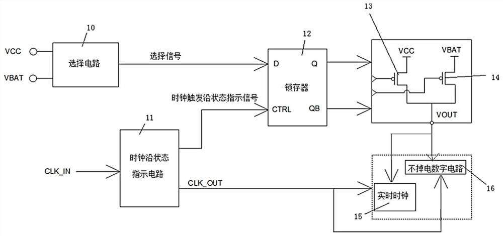
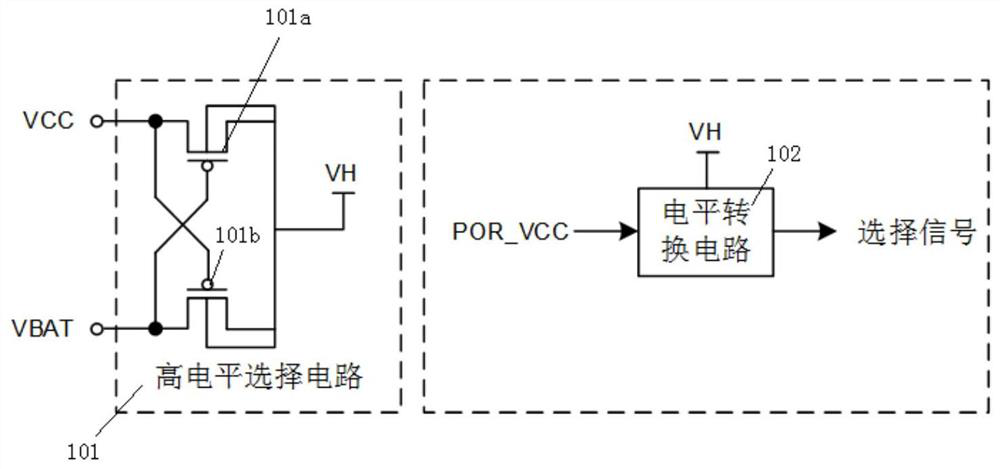
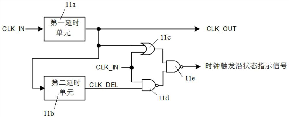
[0020] figure 1 It is a power switching circuit of a backup power domain according to an embodiment of the present invention, and the power switching circuit includes: a selection circuit 10, a clock edge state indication circuit 11, a latch 12, a first transistor 13, a second transistor 14, a real-time clock 15. Digital circuit 16 without power down.

[0021] The input terminal of the selection circuit 10 is connected to...


PUM


Abstract

The invention discloses a power supply switching circuit and method of a backup power supply domain. A first power supply and a second power supply output selection signals through a selection circuit, a clock edge state indication circuit processes a clock input signal to generate a clock output signal and a clock trigger edge state indication signal, and the clock trigger edge state indication signal is in a locked state within a period of time before and after a rising edge or a falling edge of the clock output signal. When the clock trigger edge state indication signal is in other time periods of the clock output signal, a latch is in a release state. Two outputs with opposite phases respectively control a grid electrode of a first transistor connected with the first power supply and agrid electrode of a second transistor connected with the second power supply so as to select one of the two to conduct, so the power supply is prevented from being switched at the turning edge of theclock output signal, so a digital circuit is not powered down, time sequence disorder is avoided, and reliability of backup data is improved.

Description

technical field [0001] The invention relates to the field of chip design, in particular to a power switching circuit and method for a backup power domain. Background technique [0002] In quite a lot of SoCs, when the main power supply is powered off, it is necessary to use batteries, supercapacitors or backup power supplies to the internal backup power domains of the circuit, such as real-time clock circuits, backup SRAM and other circuits to maintain power supply, so that when the main power comes on, It can maintain the continuity of timing, and can restore the state and key data of the system on chip before the power failure; therefore, the system on chip usually has two power supply ports, the main power supply and the backup power supply, but in order to ensure the longer service life of the battery in the backup power supply , when the main power supply is on, the power supply of the backup power domain is taken from the main power supply, and only when the main power...

Claims


Application Information

Patent Timeline
Patent Type & Authority Patents(China)
IPC IPC(8): H02J9/06H03K17/687
CPCH02J9/061H03K17/687Y02B70/30Y04S20/20
Inventor 王小曼侯佳力符令李德建于宝东徐立国刘畅杨立新沈冲飞白志华杨小坤黎金旺华斌
Owner BEIJING SMARTCHIP MICROELECTRONICS TECH COMPANY
Learn More