A land covering machine

A laminator and land technology, applied in plant protection cover, horticulture, botanical equipment and methods, etc., can solve the problems of high labor cost, labor and trouble, and achieve the effect of avoiding being blown away by the wind

Active Publication Date: 2021-10-22
泰安市福达农业科技有限公司
View PDF6 Cites 1 Cited by
  • Summary
  • Abstract
  • Description
  • Claims
  • Application Information

AI Technical Summary

Problems solved by technology

[0006] In order to overcome the disadvantages that two people need to hold the two ends of the plastic film to turn it, which is cumbersome and the labor cost is still high, and it is relatively laborious to move the soil to both sides of the plastic film with a hand tool to press it down, the technical problem of the present invention : To provide a kind of land mulching machine that can facilitate people to cover the plastic film on the land, and does not need to use tools to move the soil to both sides of the plastic film to press it down, which is more labor-saving

Method used


Image

  • A land covering machine
  • A land covering machine
  • A land covering machine

Examples


Embodiment 1

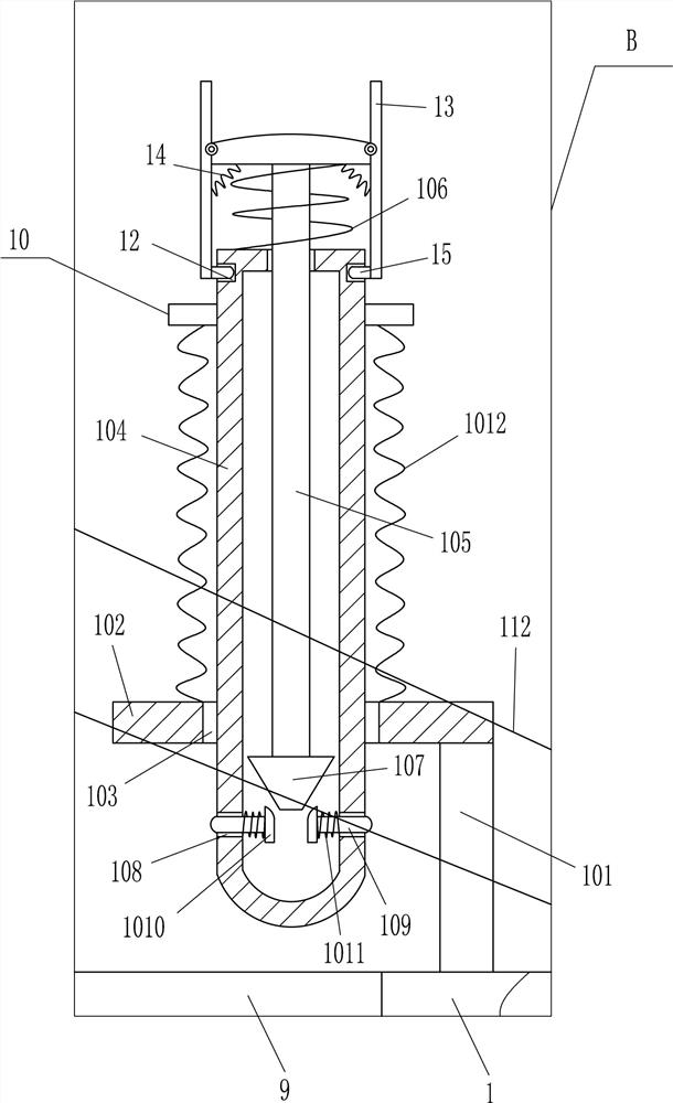
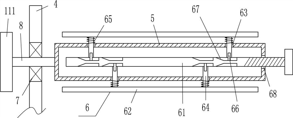
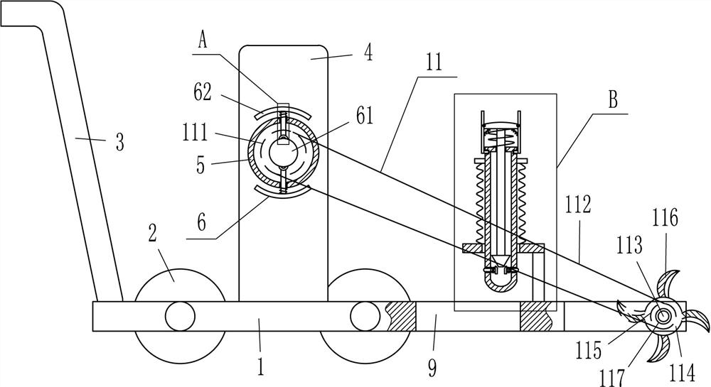
[0021] A land mulching machine such as Figure 1-4 As shown, it includes a base plate 1, wheels 2, pull rods 3, vertical plates 4, cylinder 5, fixing device 6, first bearing seat 7, rotating shaft 8 and pushing device 10, and the left part of the front and rear sides of the base plate 1 is rotating Two wheels 2 are installed, and the tie rod 3 is installed on the left side of the top of the bottom plate 1. The tie rod 3 is connected to the bottom plate 1 by welding. The first bearing seat 7 is installed, the first bearing seat 7 is connected with a rotating shaft 8, the front end of the rotating shaft 8 is fixedly connected with the cylinder body 5, the rotating shaft 8 is connected with the cylinder body 5 by welding, and the cylinder body 5 is equipped with a The fixing device 6 that the plastic film is fixed, the bottom plate 1 right part has the opening 9 that can make the plastic film pass, and the right side of the bottom plate 1 top is provided with a pusher 10 that can...

Embodiment 2

[0023] A land mulching machine such as Figure 1-4 As shown, it includes a base plate 1, wheels 2, pull rods 3, vertical plates 4, cylinder 5, fixing device 6, first bearing seat 7, rotating shaft 8 and pushing device 10, and the left part of the front and rear sides of the base plate 1 is rotating Two wheels 2 are installed, and the pull rod 3 is installed on the left side of the top of the base plate 1. A riser 4 is fixedly connected to the rear part of the top left side of the base plate 1. A first bearing seat 7 is embedded in the middle of the upper part of the riser 4. The first bearing The seat 7 is connected with a rotating shaft 8, the front end of the rotating shaft 8 is fixedly connected with a cylinder 5, the cylinder 5 is provided with a fixing device 6 for fixing the plastic film, and the right part of the base plate 1 has an opening 9 through which the plastic film can pass. The right side of the bottom plate 1 top is provided with a propulsion device 10 that ca...

Embodiment 3

[0026] A land mulching machine such as Figure 1-4As shown, it includes a base plate 1, wheels 2, pull rods 3, vertical plates 4, cylinder 5, fixing device 6, first bearing seat 7, rotating shaft 8 and pushing device 10, and the left part of the front and rear sides of the base plate 1 is rotating Two wheels 2 are installed, and the pull rod 3 is installed on the left side of the top of the base plate 1. A riser 4 is fixedly connected to the rear part of the top left side of the base plate 1. A first bearing seat 7 is embedded in the middle of the upper part of the riser 4. The first bearing The seat 7 is connected with a rotating shaft 8, the front end of the rotating shaft 8 is fixedly connected with a cylinder 5, the cylinder 5 is provided with a fixing device 6 for fixing the plastic film, and the right part of the base plate 1 has an opening 9 through which the plastic film can pass. The right side of the top of the base plate 1 is provided with a propulsion device 10 tha...


PUM


Abstract

The invention relates to a film covering machine, in particular to a land film covering machine. The technical problem of the present invention is to provide a land mulching machine that can facilitate people to cover the plastic film on the ground, and does not need to use tools to move the soil to both sides of the plastic film to press it down, which is relatively labor-saving. A land mulching machine, including a base plate, wheels, pull rods, vertical plates, a cylinder, a fixing device, a first bearing seat, etc.; two wheels are installed on the left side of the front and rear sides of the base plate in a rotating manner, and the pull rod is installed on the base plate On the left side of the top, a riser is fixedly connected to the rear part of the top left side of the bottom plate. In the present invention, the plastic film is placed on the cylinder body, fixed by an arc plate, the head end of the plastic film is pulled through the opening to move to contact with the ground, and then the plastic film is inserted into the ground through the sleeve to pull the device Move to the left to cover the plastic film on the land, without the cooperation of two people to hold the two ends of the plastic film to cover the land respectively, which is more convenient.

Description

technical field [0001] The invention relates to a film covering machine, in particular to a land film covering machine. Background technique [0002] In agricultural production, covering the land with plastic film is a new technology in agricultural production. It has the functions of increasing temperature, water retention, fertilizer retention, improving soil physical and chemical properties, increasing soil fertility, inhibiting weed growth, and reducing diseases. In the case of continuous rainfall, it also has the function of reducing humidity, thereby promoting plant growth and development, early flowering and fruiting, increasing production, reducing labor costs, etc. When crops are planted in the land, in order to ensure the growth of crops, generally Cover the ground with plastic film. [0003] At present, people hold the plastic film and cover it on the ground. Since the plastic film is rolled one by one, in order to facilitate the rotation of the plastic film to c...

Claims


Application Information

Patent Timeline
Patent Type & Authority Patents(China)
IPC IPC(8): A01G13/02
CPCA01G13/0287
Inventor 廖远峰
Owner 泰安市福达农业科技有限公司
Why Eureka
Try Eureka