Wheelchair brake

A technology for brakes and wheelchairs, applied in the field of brakes, can solve the problems of limited braking function and easy accidental sliding, and achieve the effect of preventing accidental sliding

Active Publication Date: 2020-01-03
高密市人民医院
View PDF5 Cites 2 Cited by
  • Summary
  • Abstract
  • Description
  • Claims
  • Application Information

AI Technical Summary

Problems solved by technology

[0002] Existing vehicles, such as bicycles or wheelchairs, have limited brake function and are prone to accidental sliding

Method used


Image

  • Wheelchair brake
  • Wheelchair brake
  • Wheelchair brake

Examples


Embodiment Construction

[0036] The preferred embodiments of the present invention will be described in detail below in conjunction with the accompanying drawings, so that the advantages and features of the present invention can be more easily understood by those skilled in the art, so as to define the protection scope of the present invention more clearly.

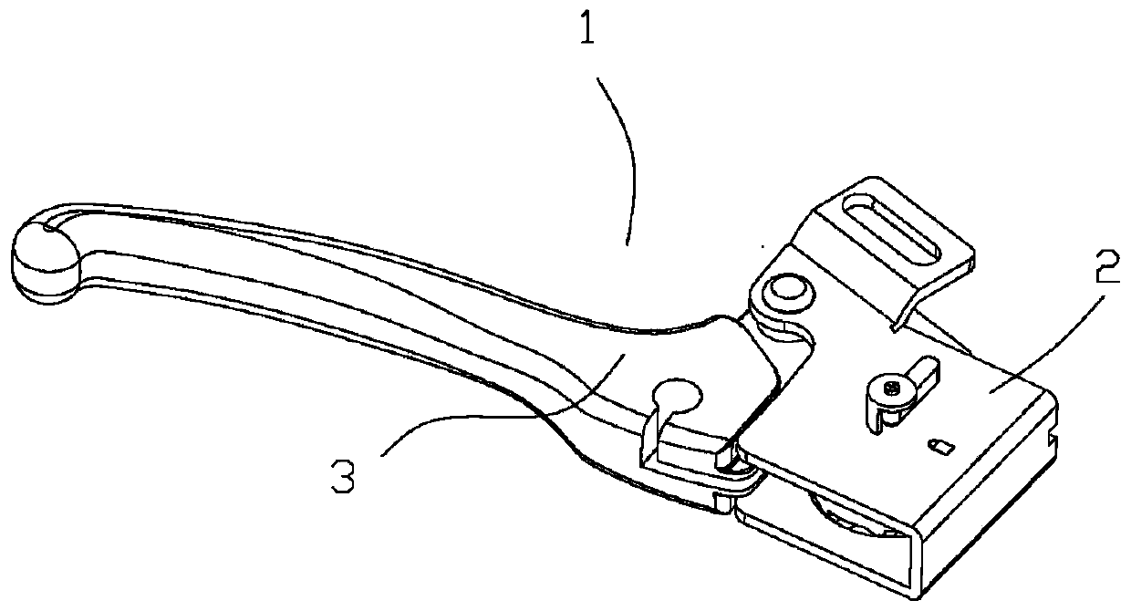
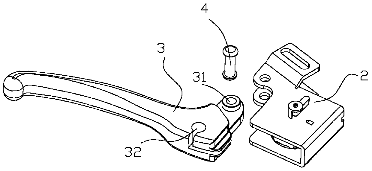
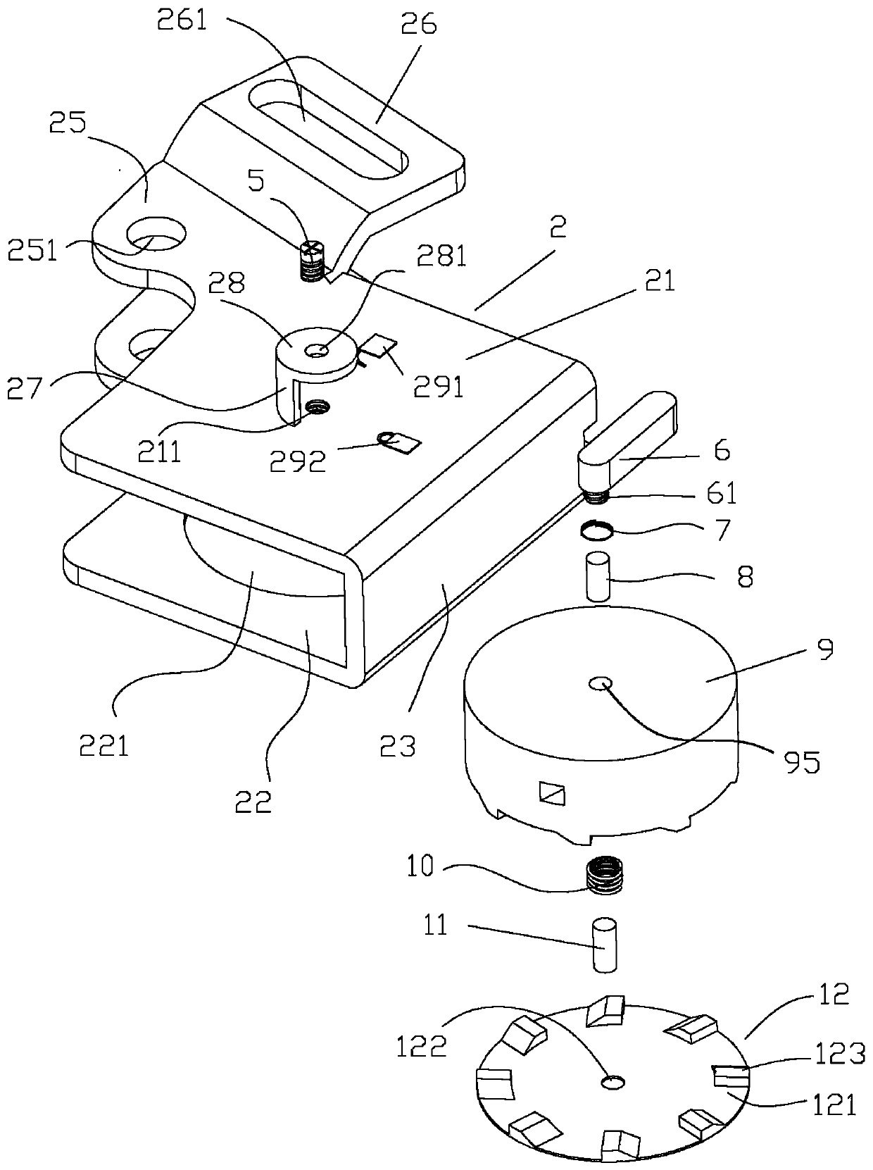
[0037] Such as Figure 1 to Figure 7 As shown, the wheelchair brake 1 includes a housing 2 and a handle 3, the housing 2 includes a first panel 21 and a second panel 22, the first panel 21 and the second panel 22 are arranged in parallel, the One side of the first panel 21 and the second panel 22 is provided with a first side panel 23 and a second side panel 24, and the edges of the first panel 21 and the second panel 22 are provided with a handle flange 25 and a handlebar projection rim 26, the handle flange 25 is provided with a first flange through hole 251, the handlebar flange 26 is provided with a second flange through hole 261, the center ...


PUM


Abstract

The invention discloses a wheelchair brake. The wheelchair brake comprises a shell and a handle, wherein a rotatable pull disc and a lock disc are arranged in the shell; a plurality of slide tooth heads are arranged on the edge of the lower surface of the pull disc in the peripheral direction; a Z-shaped wiring notch is formed inside a pulling main body; a plurality of lock tooth heads are arranged on the edge of the upper surface of the lock disc in the peripheral direction; and the lock tooth heads are matched with the slide tooth heads. After a user releases the handle, the pull disc cannotbe rotated and restored since the slide tooth heads are clamped in the lock tooth heads, and the handle is clamped in the current locking position. The wheelchair brake is safe and reliable, and caneffectively prevent a wheelchair from sliding unexpectedly.

Description

technical field [0001] The present invention relates to a brake, more precisely, a wheelchair brake. Background technique [0002] Existing vehicles, such as bicycles or wheelchairs, have very limited brakes and are prone to slipping accidentally. Contents of the invention [0003] The invention mainly solves the technical problems existing in the prior art, thereby providing a wheelchair brake. [0004] Above-mentioned technical problem of the present invention is mainly solved by following technical scheme: [0005] A wheelchair brake comprising a housing and a handle, characterized in that the housing comprises a first panel and a second panel, the first panel and the second panel are arranged in parallel, One side of the first panel and the second panel is provided with a first side panel and a second side panel, and the edges of the first panel and the second panel are provided with a handle flange and a handlebar flange, The handle flange is provided with a first ...

Claims


Application Information

Patent Timeline
Patent Type & Authority Applications(China)
IPC IPC(8): A61G5/10B62L3/02
CPCA61G5/1035B62L3/026
Inventor 不公告发明人
Owner 高密市人民医院
Why Eureka
Try Eureka