Self-adaptive pavement liquid speed bump

A self-adaptive, speed bump technology, applied in the directions of roads, roads, road signs, etc., can solve the problems of poor adaptability of speed bumps, the influence of vibration, and the inability to distinguish between rewards and punishments, so as to prevent rear-end collision accidents and improve safety.

Inactive Publication Date: 2020-01-03
陈雪
View PDF5 Cites 0 Cited by
  • Summary
  • Abstract
  • Description
  • Claims
  • Application Information

AI Technical Summary

Problems solved by technology

[0005] The invention provides an adaptive road surface liquid deceleration belt, which can automatically adapt and adjust the obstacles and vibrations caused by vehicles with different speeds, and effectively increase the distance and stability of the front and rear vehicles when passing through the deceleration belt. And the advantages of high safety, it solves the problem that the existing speed reduction belts are fixedly installed on the straight road, no matter how slow the speed of the passing vehicles is, it will inevitably cause vibrations, making the speed reduction belt Poor adaptability, unable to "distinct rewards and punishments" for passing vehicles, especially for some special vehicles that cause great harm

Method used


Image

  • Self-adaptive pavement liquid speed bump
  • Self-adaptive pavement liquid speed bump
  • Self-adaptive pavement liquid speed bump

Examples


specific Embodiment 1

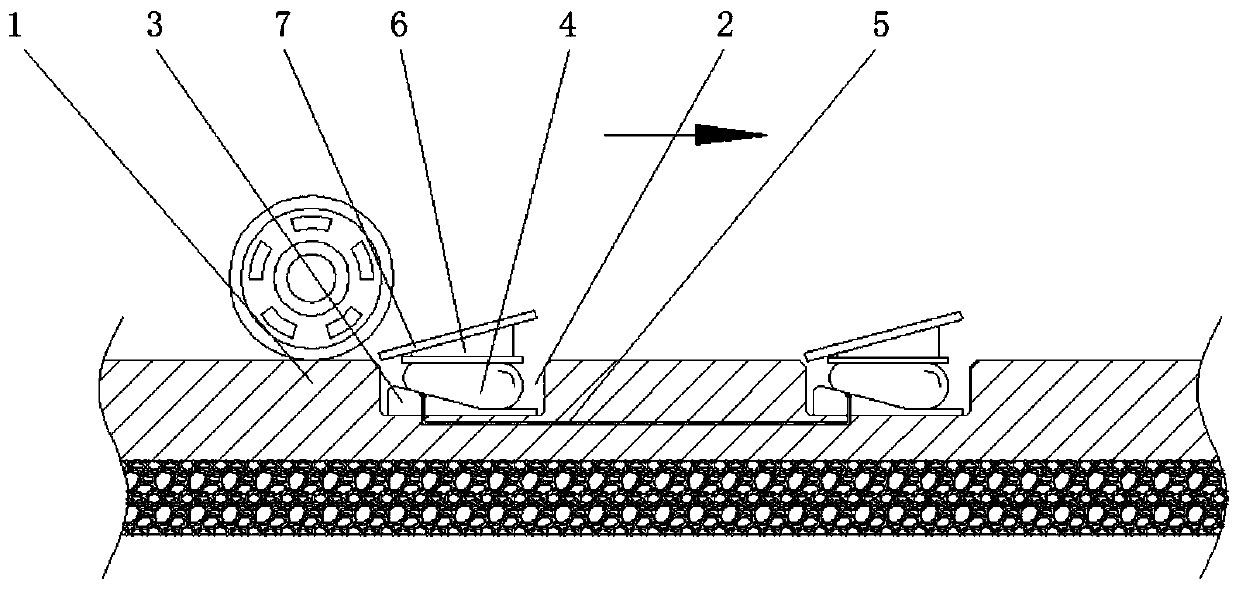
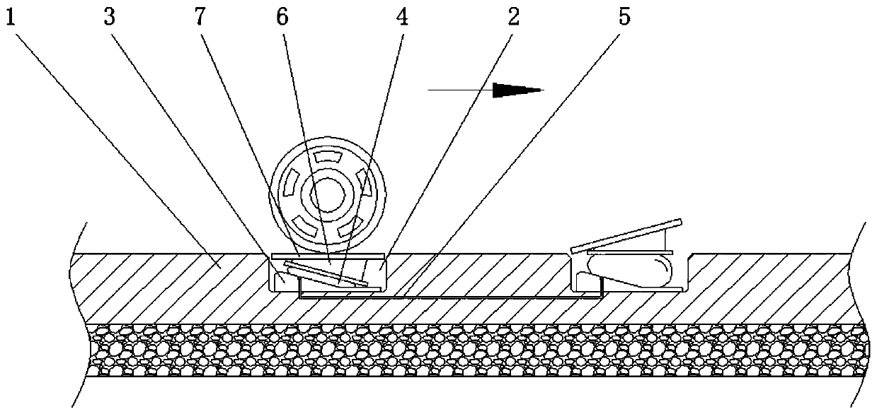
[0027] When the vehicle speed is fast, the pressure time for the pressure-bearing sealing bag 4 will be shorter, so that the hydraulic transmission oil in it cannot be compressed into another group of pressure-bearing sealing bags 4 in time and effectively, thereby causing the deceleration pressure plate 7 The inclination height is difficult to occur, and then the resistance to the vehicle is relatively large, and when the vehicle speed is slow, the pressure time for the pressure-bearing sealing bag 4 is relatively long, so that the hydraulic transmission oil in the pressure-bearing sealing bag 4 is sufficient. The time is compressed into the next group of pressure-bearing sealed capsules 4, which in turn causes the inclination angle of the deceleration plate 7 to be reduced, without forming a large hindering force on the vehicle, so that the deceleration belt can be used for vehicles with different speeds. Form the hindering force of different sizes, for example, take the exis...

specific Embodiment 2

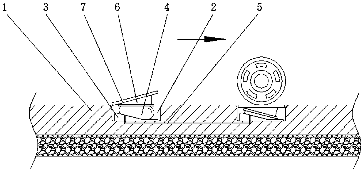
[0031] When the front vehicle drives the front deceleration plate 7 at a lower speed, and prepares to pass through the rear deceleration plate 7 at the same speed, the hydraulic transmission in the pressure sealing bag 4 will be compressed under the pressure of the front vehicle. transported to another group of pressure-bearing sealing bags 4, so that the pressure on the pressure-bearing sealing bags 4 and the deceleration plate 7 is relatively large and difficult to be compressed, resulting in greater obstruction and vibration, and then forcing the vehicles behind to have to Continue to decelerate and wait for the vehicle in front to pass, or pass the speed reduction belt at a lower speed, resulting in an increase in the distance between the front and rear vehicles, effectively improving the safety of the vehicle when passing the speed reduction belt, and preventing the rear vehicle from over-decelerating When the speed is fast, there will be a rear-end collision with the vehi...


PUM


Abstract

The invention relates to the technical field of road traffic facilities, and discloses a self-adaptive pavement liquid speed bump. The pavement speed bump comprises a driving pavement, wherein two mounting grooves are formed in the surface of the driving pavement, and lower wedge-shaped blocks are fixedly arranged at the bottoms of inner cavities of the two mounting grooves; and pressure-bearing sealing bladders are arranged at the top ends of the lower wedge-shaped blocks, and the two pressure-bearing sealing bladders communicate with each other through connecting pipelines. The self-adaptivepavement liquid speed bump, the two pressure-bearing sealing bladders and hydraulic transmission oil communication in the two pressure-bearing sealing bladders are arranged; and due to hydraulic oilhas a large viscosity, the volume of the hydraulic oil does not change suddenly when the hydraulic oil is under pressure, but the hydraulic oil is compressed and transferred to the other pressure-bearing sealing bladder gradually as the pressure time is prolonged, thereby pressing an inclined deceleration pressing plate to a state in which the inclined deceleration pressing plate is level with thedriving pavement, so that obstruction and vibration are not caused to a vehicle, and therefore the requirement that obstruction and vibration with different sizes are formed for vehicles at differentspeeds is met.

Description

technical field [0001] The invention relates to the technical field of road traffic facilities, in particular to an adaptive road surface liquid speed bump. Background technique [0002] The speed bump is a traffic facility that forces the driver to take the initiative to slow down by affecting the driver's psychological state and causing severe vibration and discomfort to the driver and occupants during the driving process of the vehicle. When passing through the deceleration belt at a higher speed, the severe vibration will cause greater damage to the chassis of the vehicle, and even scratch the chassis of the car, which will cause greater damage to the car itself, forcing the driver to actively reduce the speed. , to achieve the purpose of vehicle deceleration. [0003] However, the existing deceleration belts are all fixedly installed on a straight road, no matter how slow the speed of the passing vehicle is, it will inevitably have an impact on vibration, which makes t...

Claims


Application Information

Patent Timeline
Patent Type & Authority Applications(China)
IPC IPC(8): E01F9/529
CPCE01F9/529
Inventor 陈雪
Owner 陈雪
Why Eureka
Try Eureka