Configuration method of DC circuit breaker based on node type of converter station

A technology of DC circuit breaker and configuration method, which is applied to emergency protection circuit devices, power transmission AC networks, electrical components, etc., can solve the problems of poor economy, increase in quantity, and high cost of DCB, so as to reduce the scope of power outages and increase the stability of power supply. sexual effect

Active Publication Date: 2020-11-10
SICHUAN UNIV
View PDF4 Cites 0 Cited by
  • Summary
  • Abstract
  • Description
  • Claims
  • Application Information

AI Technical Summary

Problems solved by technology

[0003] However, with the complexity of the power grid structure, if DCBs are installed at both ends of the line, the number will increase greatly. DCBs are expensive and economical, and DC circuit breakers are installed at both ends of the DC line to achieve multi-terminal DC. In the protection method of the system, the fault current difference of each DC line in the multi-terminal DC system is not obvious, and the DC line fault is difficult to locate correctly. Therefore, it is necessary to propose a DC circuit breaker configuration method based on the node type of the converter station to solve the above problems. problem

Method used


Image

  • Configuration method of DC circuit breaker based on node type of converter station
  • Configuration method of DC circuit breaker based on node type of converter station
  • Configuration method of DC circuit breaker based on node type of converter station

Examples


Embodiment 1

[0051] Such as Figure 9 As shown, when considering the DC circuit breaker configuration method based on the node type of the converter station, the requirements for DCB configuration are as follows:

[0052] 1) Reduce investment costs as much as possible. DCB is expensive. The protection of DC power grid should reduce the number of DCB configurations as much as possible and improve the economy of the scheme while meeting the basic requirements of safe and reliable operation of the system and fast fault isolation.

[0053] 2) Minimize the scope of power failure as much as possible. When the DC grid fails, only the faulty line should be cut off from the DC grid. The most ideal effect is that the two circuit breakers at both ends of the faulty line operate to isolate the faulty line only, minimize the impact on the rest of the line, and ensure the continuity and reliability of power supply to the greatest extent.

[0054] 3) Shorten the blocking time of the converter station ...

Embodiment 2

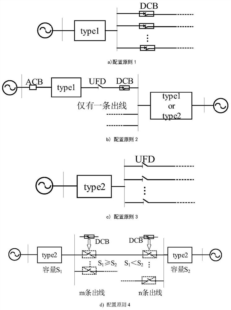
[0084] On the basis of Example 1, such as figure 1 As shown in the figure, type1 in the figure is a converter station without fault clearing capability, type2 refers to a converter station with clearing capability, and the dotted line indicates that the DCB configuration at the other end of the overhead line is configured according to the node type of the converter station at the port.

[0085] The specific configuration method is described as follows:

[0086] 1) When there are multiple outgoing lines at the outlet of a node that does not have the ability to clear DC faults, install a DCB at the exit of each line, such as figure 1 a) as shown;

[0087] 2) When a node without fault clearing capability is connected to the AC system, and there is only one outgoing line at the outlet, since this node has a relatively small impact on the entire DC grid, for economic considerations, only at the far end of the line (near the other A node) to install a DCB, and install a UFD at the...


PUM


Abstract

The invention discloses a DC circuit breaker configuration method based on the node type of a converter station. When one end of a node that does not have the ability to clear DC faults is connected to an AC system, and there are multiple outlets at the outlet of the node, a DCB is installed on each outlet. ; When one end of the node without DC fault clearing capability is connected to the AC system, and there is only one outgoing line at the outlet of the node, install a DCB near the other node and a UFD near the node; when there is a DC fault When one end of the node with clearing ability is connected to the AC system, and there are multiple outgoing lines at the outlet of the node, a UFD should be installed at each outgoing line; when any two nodes with the ability to clear DC faults are connected, an additional One DCB; when the DCB and UFD are installed at the same location, only the DCB is reserved, and there is no need to install an additional UFD. The invention makes full use of the action characteristics of the converter station type, DCB and UFD, and the three cooperate with each other to isolate faults.

Description

technical field [0001] The invention belongs to the technical field of electric power testing and instruments, and in particular relates to a DC circuit breaker configuration method based on the node type of a converter station. Background technique [0002] Driven by the "Full Energy Interconnection" plan, the converter stations that make up the DC power grid may be combined in the following three ways: all converter stations without fault-clearing capabilities, all converter stations with fault-clearing capabilities, or both. There are all kinds of converter stations. For a power grid with a fault-clearing capacity circulating station, when a fault occurs, only the converter station at the fault end cannot clear the fault, and the other converter stations continue to feed energy to the fault point through the DC line in the mesh. All converter stations need to interrupt power transmission for a short time, but this will lead to power changes on the AC side, frequency chan...

Claims


Application Information

Patent Timeline
Patent Type & Authority Patents(China)
IPC IPC(8): H02H7/26H02H7/28H02J3/36
CPCH02H7/268H02H7/28H02J3/36Y02E60/60
Inventor 王渝红凌楠曾琦刘程卓石富童刘进飞邰克强
Owner SICHUAN UNIV
Why Eureka
Try Eureka