Detachable standard connecting piece for door and window outer frame and auxiliary frame

A detachable, connecting piece technology, applied in the direction of connecting components, pins, mechanical equipment, etc., can solve the problems of long installation time, low efficiency, unable to fully realize standardized operation, etc., and achieve the effect of preventing rotation and simplifying the installation process.

Pending Publication Date: 2020-01-07
常州玖洲联横建材有限公司
View PDF0 Cites 0 Cited by
  • Summary
  • Abstract
  • Description
  • Claims
  • Application Information

AI Technical Summary

Problems solved by technology

The existing door and window installation method is to fix the outer frame of the door and window on the attached frame or wall through fasteners or screws. With the increase of the service life of the building, settlement displacement will occur or the door and window will be deformed with shrinkage, such as plastic steel material , even breakage in

Method used


Image

  • Detachable standard connecting piece for door and window outer frame and auxiliary frame
  • Detachable standard connecting piece for door and window outer frame and auxiliary frame
  • Detachable standard connecting piece for door and window outer frame and auxiliary frame

Examples


Embodiment 1

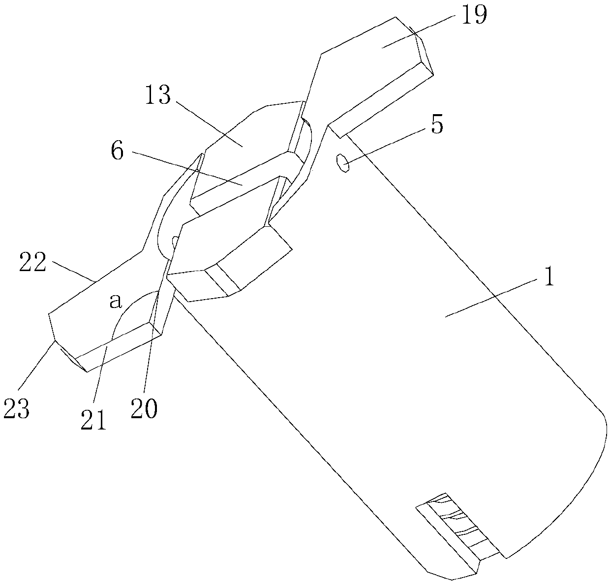
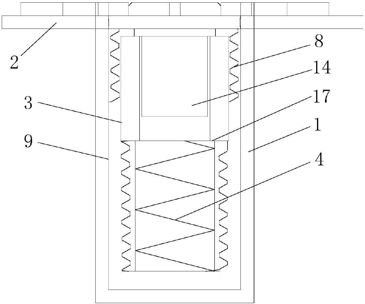
[0032] See Figure 1 to Figure 4 , the present invention has a shaft sleeve 1, a positioning pin 2 and an inner shaft 3; a spring 4 is provided at the bottom end of the inner cavity of the shaft sleeve 1, and a pair of through holes 5 are provided at the opening position of the upper part; an inner shaft 3 is connected to the upper part of the spring 4; The top of the shaft 3 has a slot 6 corresponding to the through hole 5, and the inner shaft 3 is fixed inside the shaft sleeve 1 through the positioning pin 2 inserted in the through hole 5 of the shaft sleeve 1, and the top of the inner shaft 3 is aligned with the shaft sleeve. 1. The end face of the opening end is flush; the inner shaft 3 has an inner shaft external thread 7 on the lower circumference surface; The surface is glossy 9.

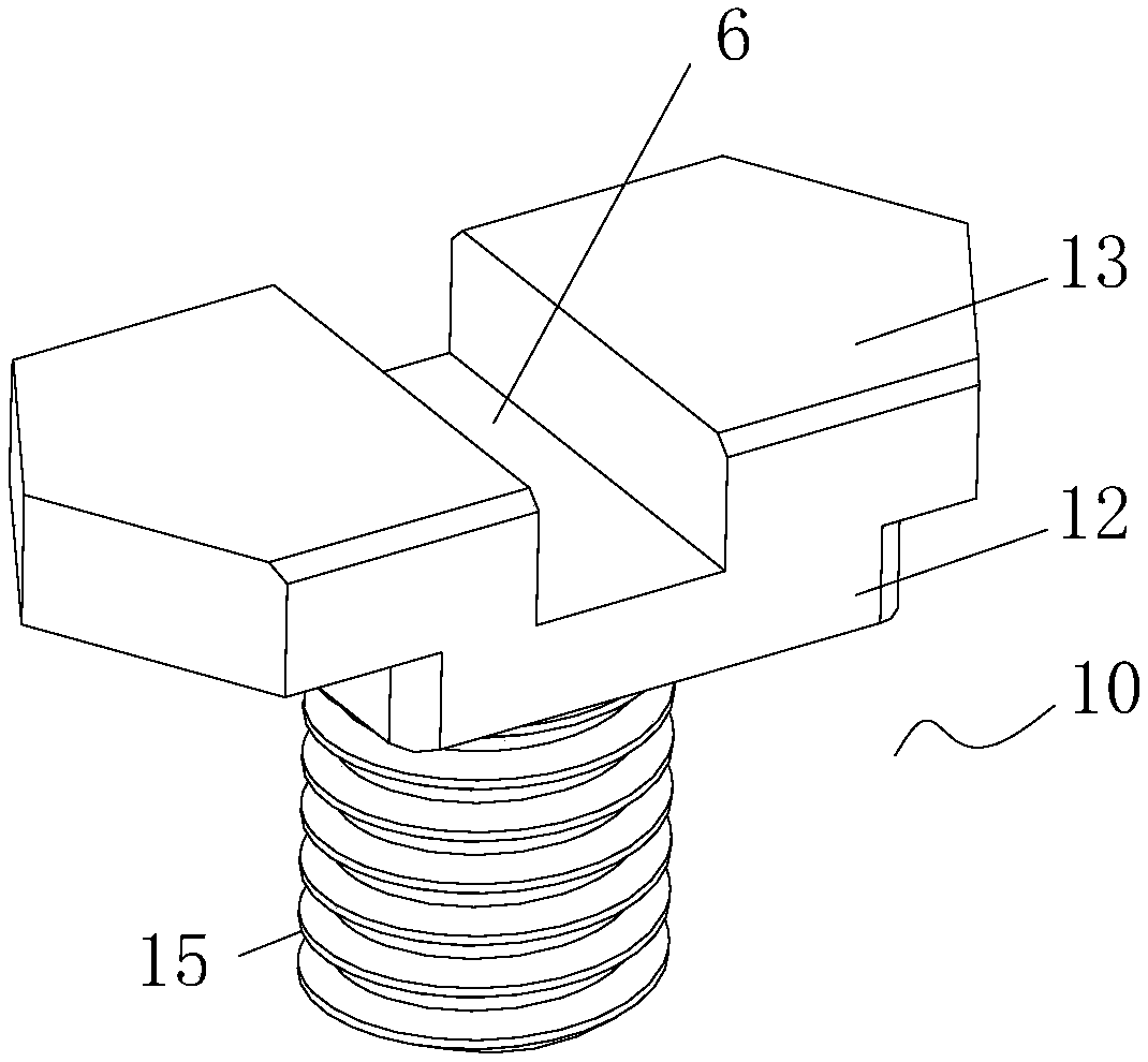
[0033] See Figure 10 , the inner shaft 3 is an up-and-down structure, which is divided into an inner shaft upper body 10 and an inner shaft lower body 11; the inner shaft upper body 10 and...

Embodiment 2

[0038] See Figure 5 and Image 6 , the present invention has a shaft sleeve 1, a positioning pin 2 and an inner shaft 3; a spring 4 is provided at the bottom end of the inner cavity of the shaft sleeve 1, and a pair of through holes 5 are provided at the opening position of the upper part; an inner shaft 3 is connected to the upper part of the spring 4; The top of the shaft 3 has a slot 6 corresponding to the through hole 5, and the inner shaft 3 is fixed inside the shaft sleeve 1 through the positioning pin 2 inserted in the through hole 5 of the shaft sleeve 1, and the top of the inner shaft 3 is aligned with the shaft sleeve. 1. The end face of the opening end is flush; the inner shaft 3 has an inner shaft external thread 7 on the lower circumference surface; The surface is glossy 9.

[0039] See image 3 , Figure 4 and Figure 9 , the inner shaft 3 is a combined upper and lower body, which is divided into an inner shaft upper body 10 and an inner shaft lower body 11...

Embodiment 3

[0042] See Figure 1 to Figure 4, the present invention has a shaft sleeve 1, a positioning pin 2 and an inner shaft 3; a spring 4 is provided at the bottom end of the inner cavity of the shaft sleeve 1, and a pair of through holes 5 are provided at the opening position of the upper part; an inner shaft 3 is connected to the upper part of the spring 4; The top of the shaft 3 has a slot 6 corresponding to the through hole 5, and the inner shaft 3 is fixed inside the shaft sleeve 1 through the positioning pin 2 inserted in the through hole 5 of the shaft sleeve 1, and the top of the inner shaft 3 is aligned with the shaft sleeve. 1. The end face of the opening end is flush; the inner shaft 3 has an inner shaft external thread 7 on the lower circumference surface; The surface is glossy 9.

[0043] See image 3 , Figure 4 and Figure 9 , the inner shaft 3 is a combined upper and lower body, which is divided into an inner shaft upper body 10 and an inner shaft lower body 11; t...


PUM


Abstract

The invention relates to a detachable standard connecting piece for a door and window outer frame and an auxiliary frame. The standard connecting piece is provided with a shaft sleeve, a positioning pin and an inner shaft; a spring is arranged at the bottom end of an inner cavity of the shaft sleeve, and a pair of through holes are formed in an upper opening; the inner shaft is connected to the upper portion of the spring; the top of the inner shaft is provided with slotted holes corresponding to the through holes, the inner shaft is fixed into the shaft sleeve through positioning pins alternately arranged inside the through holes in the shaft sleeve, and the top of the inner shaft is flush with the end face of the opening end of the shaft sleeve; the inner shaft is of a vertical combinedstructure and is divided into an upper inner shaft body and a lower inner shaft body; the upper inner shaft body is in threaded connection with the lower inner shaft body. The connecting piece is usedfor connecting the auxiliary frame with the door and window outer frame, standardized installation is achieved, the installation process is simple, and the inner shaft is popped up and inserted intoa reserved hole in the outer frame and is rotated counterclockwise by 90 degrees to complete installation; wind loads of doors and windows, displacement and sedimentation buildings or thermal expansion and cold contraction of the doors and windows and the like are mainly avoided, the certain space allowance exists, and therefore no deformation to doors and windows is caused.

Description

technical field [0001] The invention relates to components for building installation, in particular to a detachable standard connector between the outer frame of a door and window and an auxiliary frame. Background technique [0002] With the rapid development of my country's construction industry, the construction quality and use requirements have also been improved accordingly, and the use requirements for the correspondingly installed doors and windows have also been greatly improved. The existing door and window installation method is to fix the outer frame of the door and window on the attached frame or wall through fasteners or screws. With the increase of the service life of the building, settlement displacement will occur or the door and window will be deformed with shrinkage, such as plastic steel material , and even breakage in severe cases. [0003] The existing installation method requires manual judgment of the positions of the outer frame and the attached fram...

Claims


Application Information

Patent Timeline
IPC IPC(8): F16B13/10
CPCF16B13/08
Inventor 王兴栋
Owner 常州玖洲联横建材有限公司
Why Eureka
Try Eureka