Packaging equipment for cable sheath material

A cable sheathing material and packaging equipment technology, applied in the field of cable processing, can solve problems such as troublesome use, large differences in the regularity of packaging bags, trouble, etc. Effect

Active Publication Date: 2020-01-10
SUZHOU HENGLI COMM MATERIAL +1
View PDF10 Cites 0 Cited by
  • Summary
  • Abstract
  • Description
  • Claims
  • Application Information

AI Technical Summary

Problems solved by technology

[0003] However, in the existing packaging bag forming devices, the forming device is generally set in a box shape, which is not only troublesome to use, but also has a large difference in the regularity of the packed packaging bag, and it is very difficult to design different forming devices according to different packaging requirements. trouble

Method used


Image

  • Packaging equipment for cable sheath material
  • Packaging equipment for cable sheath material
  • Packaging equipment for cable sheath material

Examples


Embodiment 1

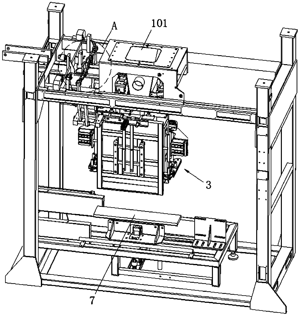
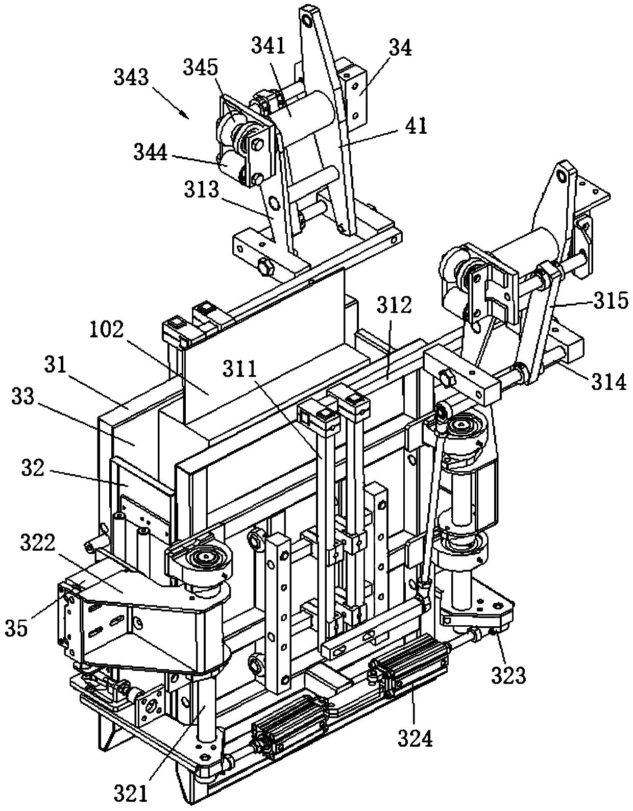
[0025] Embodiment 1: a kind of packaging equipment for cable sheath material, refer to the attached Figure 1-3 The forming mechanism 3 located below the hopper 101 includes two first forming plates 31, two second forming plates 32 and guide rails 301, and the first forming plates 31 and the second forming plates 32 are installed on the guide rails through a connecting seat 34 301, the second forming plate 32 is located between the two first forming plates 31, and the first forming plate 31 and the second forming plate 32 form a forming cavity 33 for forming the packaging bag 102. The forming A support plate 7 is installed directly below the mechanism 3, and the support plate 7 is located below the forming mechanism 3;

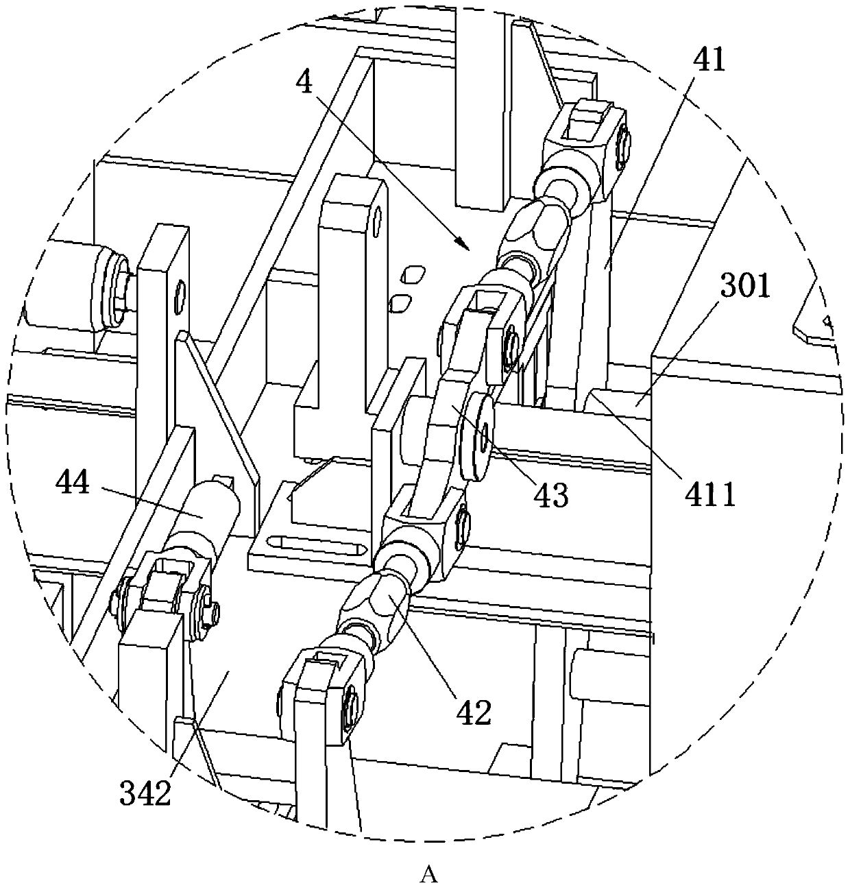
[0026] There are two guide rails 301 and connecting seats 34, the second forming plate 32 is installed on the first forming plate 31, a driving assembly 4 is arranged between the two connecting seats 34, and a rotating plate 41 The two ends are respectively c...

Embodiment 2

[0030] Embodiment 2: a kind of packaging equipment for cable sheath material, with reference to the attached Figure 1-3The forming mechanism 3 located below the hopper 101 includes two first forming plates 31, two second forming plates 32 and guide rails 301, and the first forming plates 31 and the second forming plates 32 are installed on the guide rails through a connecting seat 34 301, the second forming plate 32 is located between the two first forming plates 31, and the first forming plate 31 and the second forming plate 32 form a forming cavity 33 for forming the packaging bag 102. The forming A support plate 7 is installed directly below the mechanism 3, and the support plate 7 is located below the forming mechanism 3;

[0031] There are two guide rails 301 and connecting seats 34, the second forming plate 32 is installed on the first forming plate 31, a driving assembly 4 is arranged between the two connecting seats 34, and a rotating plate 41 The two ends are respec...


PUM


Abstract

The invention discloses packaging equipment for a cable sheath material. A forming mechanism located below a hopper comprises two first forming plates, two second forming plates and a guide rail. Thefirst forming plates and the second forming plates are mounted on the guide rail through a connecting seat, the second forming plates are located between the two first forming plates, the first forming plates and the second forming plates encircle a forming cavity where a packaging bag is formed, two ends of a rotating plate are separately connected to a driving assembly and the first forming plates, a rotating hole where the guide rail penetrates through is formed in the rotating plate, second rotating rods are mounted on two sides of the first forming plates, the second forming plates are mounted on a second rotating rod, and the second forming plates are mounted on a second connecting plate through a first extrusion air cylinder. The packaging equipment not only can prevent a material from being accumulated irregularly at a corner to affect the regularity of a packaging structure, but also is convenient for staff to adjust and replace the first and second forming plates and adjust the thickness and width of the forming cavity so as to fit packaging demands of different specifications.

Description

technical field [0001] The invention relates to a packaging device for cable sheath materials, belonging to the technical field of cable processing. Background technique [0002] Plastics for wire and cable insulation and sheathing are commonly known as cable materials, which include rubber, plastic, nylon and other varieties. After the production of cable materials, packaging bags are required to encapsulate the material particles. On the one hand, it can isolate the outside The adverse effects of the environment on materials can also be formed into a regular packaging structure, which is convenient for stacking and transportation. [0003] However, in the existing packaging bag forming devices, the forming device is generally set in a box shape, which is not only troublesome to use, but also has a large difference in the regularity of the packed packaging bag, and it is very difficult to design different forming devices according to different packaging requirements. troub...

Claims


Application Information

Patent Timeline
Patent Type & Authority Applications(China)
IPC IPC(8): B65B59/00B65B1/00B65B61/24
CPCB65B1/00B65B59/00B65B61/24
Inventor 水国华金立楼计成栋徐明锋徐明英
Owner SUZHOU HENGLI COMM MATERIAL
Why Eureka
Try Eureka