Steel moving and conveying system

A conveying system and material moving technology, applied in the field of steel rolling production, can solve the problems of affecting the service life of conveying rollers, unfavorable cold shear sizing by cross-stacking, etc., so as to achieve the effect of not affecting work efficiency, increasing the scope of application, and avoiding system shutdown.

Pending Publication Date: 2020-01-10
SHANDONG IRON & STEEL CO LTD
View PDF0 Cites 3 Cited by
  • Summary
  • Abstract
  • Description
  • Claims
  • Application Information

AI Technical Summary

Problems solved by technology

[0004] The purpose of the present invention is to provide a material transfer conveying system to at least solve the problem that cross-stacking of long steel bars is not conducive to the subsequent cold shearing and si

Method used


Image

  • Steel moving and conveying system
  • Steel moving and conveying system
  • Steel moving and conveying system

Examples


Embodiment Construction

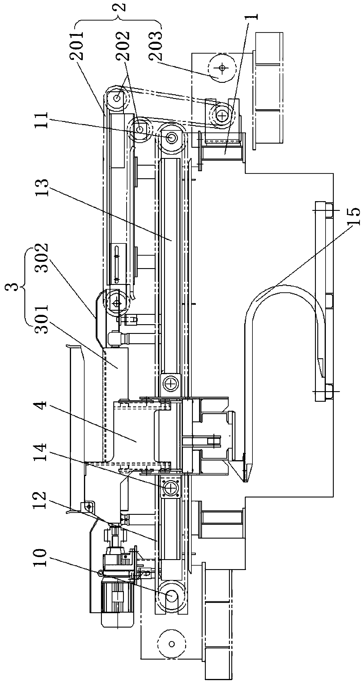
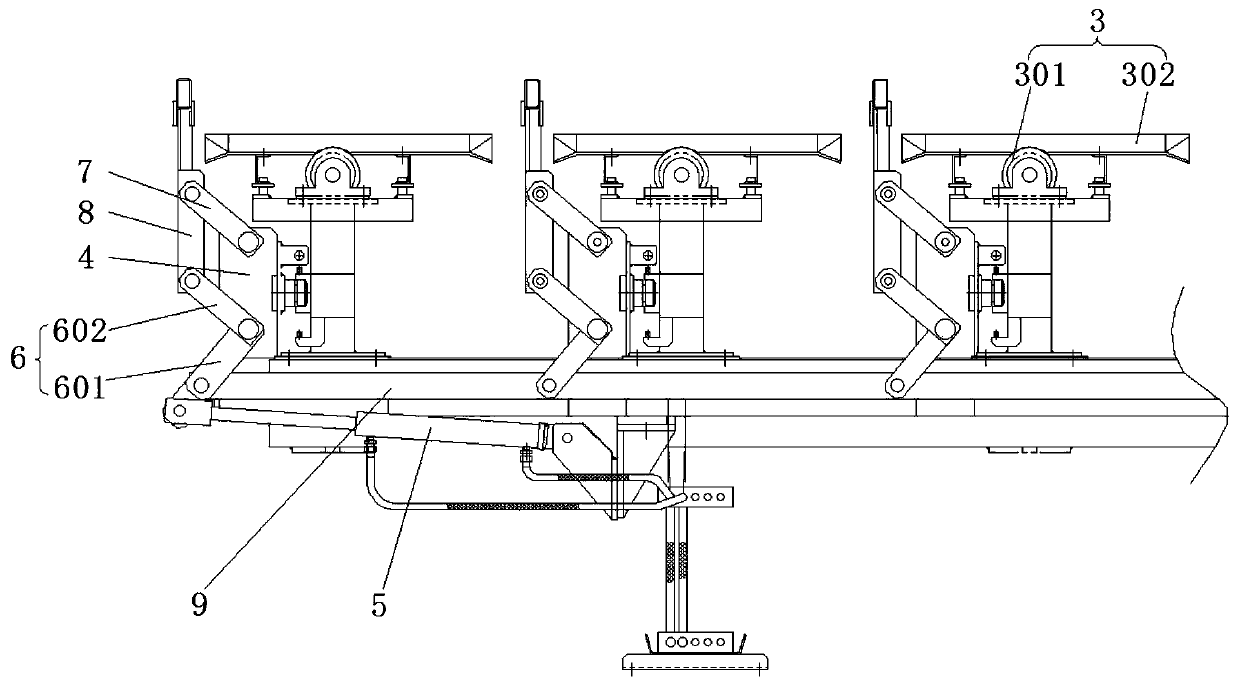
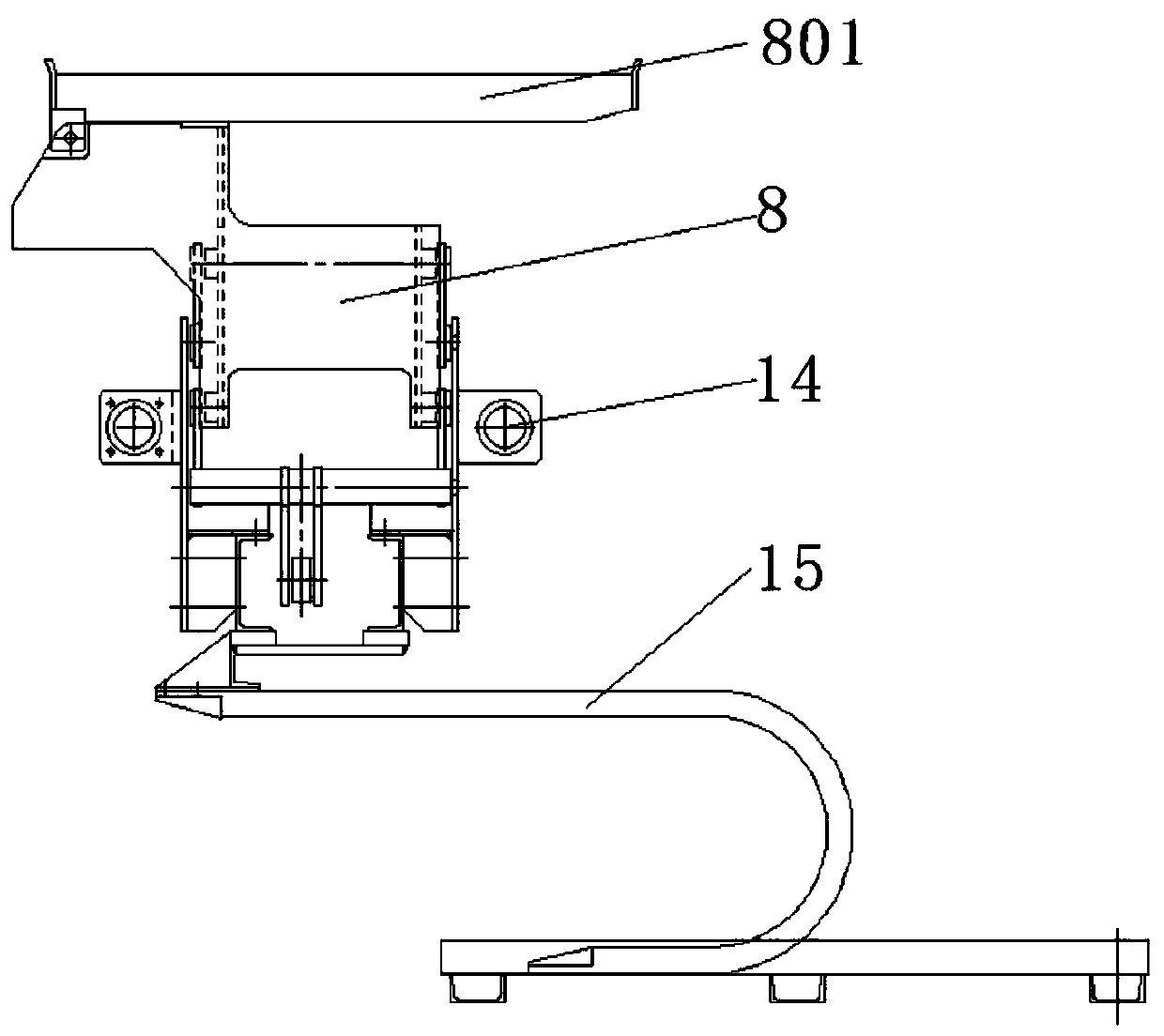
[0024] The present invention will be described in detail below with reference to the accompanying drawings and examples. It should be noted that, in the case of no conflict, the embodiments of the present invention and the features in the embodiments can be combined with each other.

[0025] In the description of the present invention, the terms "longitudinal", "transverse", "upper", "lower", "front", "rear", "left", "right", "vertical", "horizontal", " The orientations or positional relationships indicated by "top", "bottom", etc. are based on the orientations or positional relationships shown in the drawings, and are only for the convenience of describing the present invention and do not require that the present invention must be constructed and operated in a specific orientation, so they cannot be understood as Limitations on the Invention. The terms "connected" and "connected" used in the present invention should be understood in a broad sense, for example, it can be fixe...


PUM


Abstract

The invention belongs to the technical field of steel rolling production, and particularly relates to a steel moving and conveying system. The system comprises a conveying chain platform, conveying roller beds and steel moving trolleys, wherein each conveying roller bed comprises a plurality of conveying rollers which are arranged in parallel; the conveying chain platform is arranged on one sidesof the conveying roller beds and comprises a plurality of conveying chains which are parallel to one another; the steel moving trolleys move along a guide device to drive lifting mechanisms on the steel moving trolleys to shuttle between the adjacent conveying rollers and between the adjacent conveying chains; the lifting mechanisms on the steel moving trolleys can automatically expand and contract to lift and move bars; and through the adoption of C-shaped brackets, system shutdown caused by bar stacking of the conveying chain platform is avoided. According to the steel moving and conveying system, a connecting rod is used for connecting driving parts on the plurality of steel moving trolleys together, and the plurality of lifting mechanisms are driven to move by a hydraulic cylinder, sothat the consistency of the lifting and the moving is ensured, the deformation of the bars is avoided, the structure of the system is simpler, and the manufacturing and maintenance costs are reduced.

Description

technical field [0001] The invention belongs to the technical field of steel rolling production, and in particular relates to a material transfer conveying system. Background technique [0002] In the process of steel bar production, it is necessary to transport the long steel bars on the cooling bed to the cold shearing place and cut them into national standard scales. At present, the common method is to use multiple flat supporting mechanisms. The supporting plates of the flat dragging mechanisms are connected to one end of the connecting rod, and the connecting rod The other end is hinged to the fixed point, and the driving device drives the connecting rod to swing around the other end, so that the supporting plate revolves around the above fixed point (the supporting plate is always kept horizontal), and the long steel bars are moved to the conveying roller table, and passed through the conveying roller. The steel bar is transported to the cold shearing platform for fixe...

Claims


Application Information

Patent Timeline
IPC IPC(8): B65G17/38B65G23/44
CPCB65G17/38B65G23/44
Inventor 卢正臻关中华杨风滨孙圣刚彭国胜刘琮训王建伟卢雅涵刘彬付乐赵珊珊胡阳杨文佳冯霞
Owner SHANDONG IRON & STEEL CO LTD
Why Eureka
Try Eureka