A bottom sill structure for stilling pools

A stilling pool floor, stilling pool technology, applied in marine engineering, construction, barrage/weir, etc., can solve the problems of cavitation, impact damage, insufficient energy dissipation of water flow, etc.

Inactive Publication Date: 2021-02-02
李洪涛
View PDF6 Cites 0 Cited by
  • Summary
  • Abstract
  • Description
  • Claims
  • Application Information

AI Technical Summary

Problems solved by technology

However, the problem with the bottom sill in this patent is that the energy dissipation of the water flow is insufficient, so that the water flow easily hits the bottom plate and the tail sill, causing cavitation or impact damage to the bottom plate or the tail sill
However, in this structure, a folded plate is set at the tail sill, so the depth of the stilling basin needs to be increased
Moreover, the water flow needs to cross the tail sill to reach the apron, so that the water at the tail sill cannot flow smoothly into the apron, and it will cause impact damage or cavitation at the tail sill

Method used


Image

  • A bottom sill structure for stilling pools
  • A bottom sill structure for stilling pools
  • A bottom sill structure for stilling pools

Examples


Embodiment

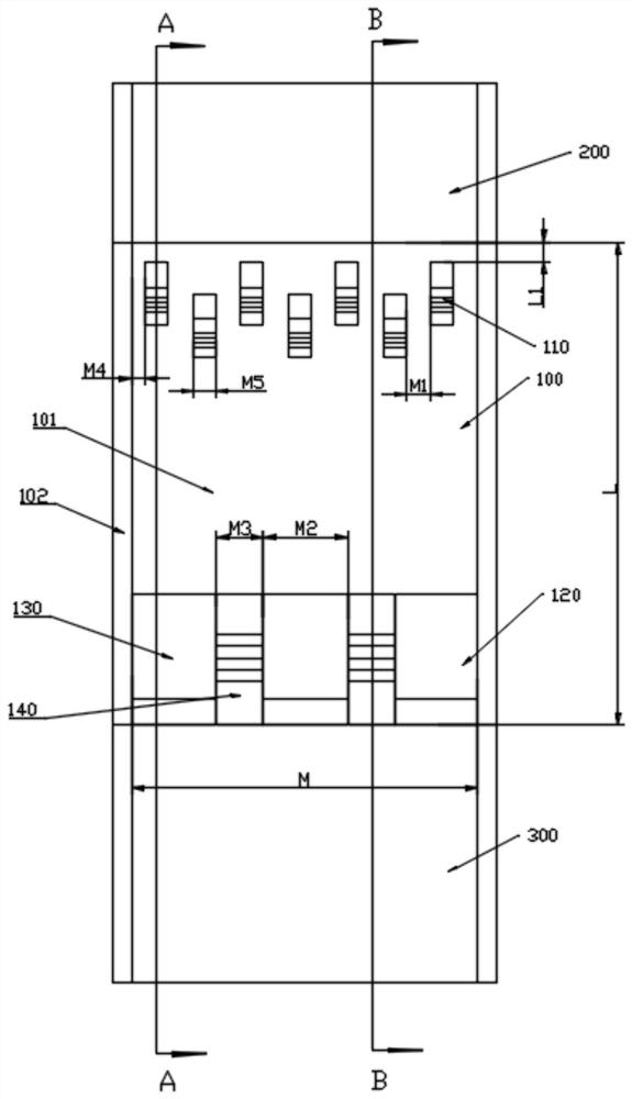
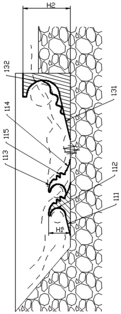
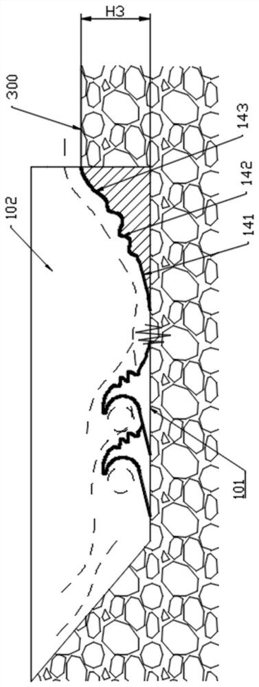
[0024] Example: such as Figure 1-3 As shown, a stilling basin 100 includes a stilling basin bottom plate 101 and a stilling basin side plate 102 . The upstream part of the stilling basin is connected to the overflow tank 200, the downstream part of the stilling basin is connected to the apron 300, and the depth of the stilling basin is greater than that of the apron. A front bottom sill 110 at the upstream part and a rear bottom sill 120 at the downstream part are arranged on the floor of the stilling basin. The front bottom sill is opposite to the overflow tank, and is used to reduce the kinetic energy of the water flowing down from the overflow tank. The tail sill is arranged between the stilling basin and the apron, and is used to further dissipate the energy of the water flow downstream of the stilling basin and make it flow into the apron smoothly, reducing the length of the apron.

[0025] In this embodiment, the front bottom sills 110 are divided into two rows along ...


PUM


Abstract

The invention discloses a bottom sill structure for a stilling basin, which comprises a front bottom sill arranged on the bottom plate of the stilling basin and connected to the tail of an overflow tank, and a bottom sill arranged on the tail of the stilling basin bottom and connected to the tail of the overflow tank. The rear bottom sill connected with the apron; the upstream flow direction of the front bottom sill includes the first climbing section and the first concave arc section connected with the first climbing section, the front bottom sill The backwater flow direction includes a downhill section, and the downhill section includes a first upward convex arc section, a first concave-convex arc section and a first downward concave arc section. The tail bottom sill includes a buffer convoluted portion and a slow flow portion arranged at intervals along the width direction of the stilling basin, and the buffer convoluted portion includes a second climbing section and a second concave arc section connected with the second climbing section , the slow flow portion includes a second downward concave arc segment, a second concave-convex arc segment and a second upward convex arc segment. The bottom sill structure of the stilling pool of the present invention has good energy dissipation effect and makes water flow into the apron more smoothly.

Description

technical field [0001] The invention relates to energy dissipating equipment in water conservancy projects, in particular to a stilling pool and its bottom sill structure. Background technique [0002] Stilling pool is an energy dissipation facility used in water conservancy and hydropower projects to promote the generation of underflow hydraulic jumps downstream of discharge structures. The stilling pool can quickly change the rapid flow of the discharge into a slow flow. Generally, it can partially eliminate the kinetic energy of the discharge flow and shorten the length of the apron. It is an effective and economical energy dissipation facility. The stilling basin generally includes the stilling basin bottom plate connected with the overflow tank, the stilling basin side plates arranged on both sides of the stilling basin bottom plate, the stilling basin tail sill arranged at the end of the stilling basin, the tail of the stilling basin After the hurdle, set up the apron...

Claims


Application Information

Patent Timeline
Patent Type & Authority Patents(China)
IPC IPC(8): E02B8/06
CPCE02B8/06
Inventor 李洪涛侯晓翠乔蓉芳薛新丽张欣
Owner 李洪涛
Why Eureka
Try Eureka