
Seat footrest structure and seat

A seat and footrest technology, applied to chairs, other seating furniture, stools, etc., can solve the problems of small seat design space, complex structural design, inconvenient operation, etc., achieve convenient modular design, improve user experience, The effect of locking state stability

Inactive Publication Date: 2020-01-17
UE FURNITURE CO LTD
View PDF0 Cites 1 Cited by
  • Summary
  • Abstract
  • Description
  • Claims
  • Application Information

AI Technical Summary

Problems solved by technology

[0002] At present, there are more and more seats with footrest function on the market, but the structure design of these footrests is generally complex, inconvenient to operate, bulky, very heavy, high production cost, and the overall design space of the seat is small, Narrow application range and other problems; specifically, the current footrest structure often uses at least two switches to realize the flipping of the footrest. At the same time, multiple parts are turned over simultaneously during the flipping process. Large, after the footrest is folded, it often occupies a lot of space under the seat, which makes it more difficult to set other functions under the seat, which in turn makes the seat have a single function, bulky and unsightly appearance

Method used


Image

  • Seat footrest structure and seat
  • Seat footrest structure and seat
  • Seat footrest structure and seat

Examples


Embodiment

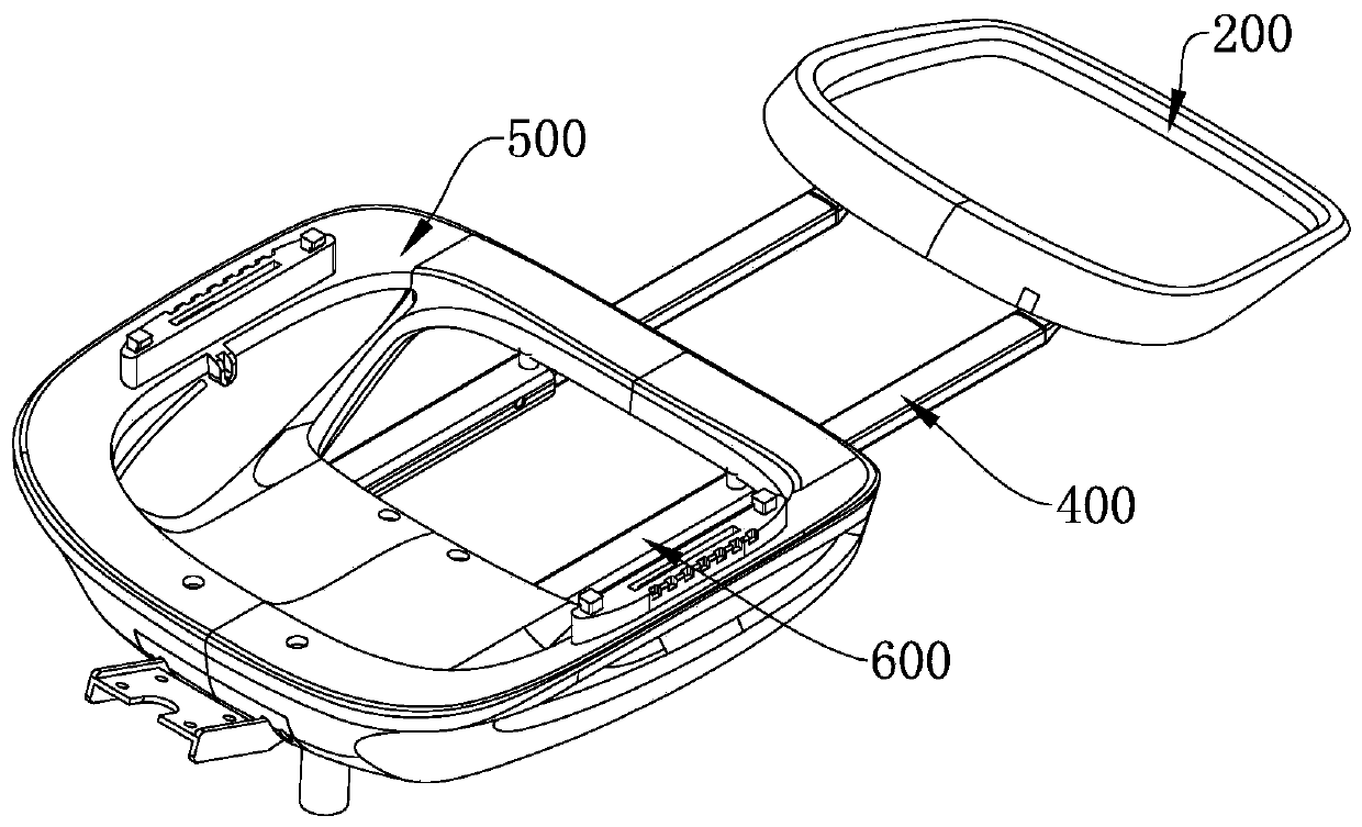
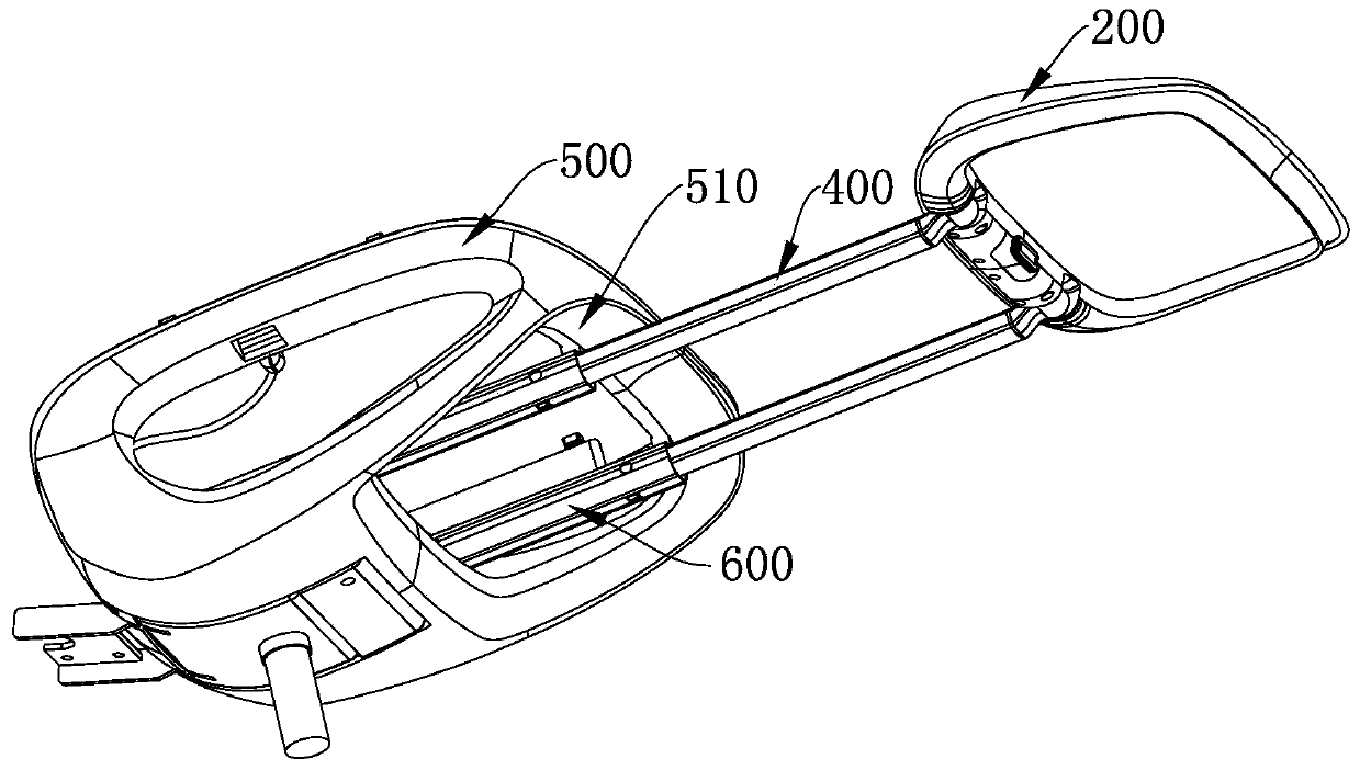
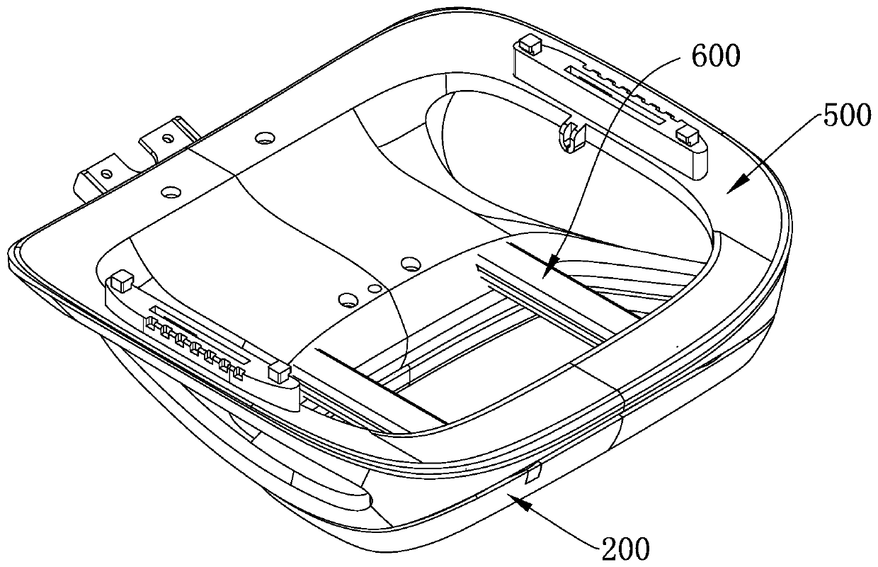
[0077] A seat footrest structure, such as Figure 1~29 shown, including:

[0078] A support shaft 100, the support shaft 100 has a first locking position 110 and a second locking position 120 along the circumferential direction, and the support shaft 100 is specifically a hexagonal shaft;

[0079] footrest 200, such as Figure 8 , 20 As shown in , 21, the footrest 200 includes a root end 270 and a free end 280 which are arranged oppositely, and an accommodation cavity 210 for accommodating the support shaft 100 is opened on the root end 270, and the footrest 200 can rotate relative to the support shaft 100;

[0080] The movable locking part 300 is arranged in the accommodation cavity 210 of the footrest 200, the movable locking part 300 moves along the radial direction of the support shaft 100, and the footrest 200 rotates until the movable locking part 300 and When the first locking position 110 or the second locking position 120 is engaged, the footrest 200 and the suppor...


PUM


Abstract

The invention relates to a seat footrest structure and a seat, and the footrest structure comprises: a supporting shaft which is provided with a first locking position and a second locking position along the circumferential direction; a footrest that comprises a root end and a free end which are oppositely arranged, wherein a containing cavity for containing the supporting shaft is formed in the root end, and the footrest can rotate relative to the supporting shaft; a movable locking piece that is arranged in the containing cavity of the footrest; the movable locking piece moves in the radialdirection of the supporting shaft, and when the footrest rotates to the position where the movable locking piece is connected with the first locking position and the second locking position, the footrest and the supporting shaft are kept relatively fixed, and the footrest is in a locked state; when the movable locking piece is separated from the first locking position and the second locking position, the footrest is in an unlocked state and rotates around the supporting shaft; the invention discloses the seat. The footrest can be folded below the seat part. Compared with the prior art, the seat footrest structure has the advantages of being compact and simple in structure, convenient to operate, small in occupied space, more convenient to modulate, wider in application range and concise and attractive in appearance.

Description

technical field [0001] The invention belongs to the technical field of furniture equipment, and in particular relates to a seat footrest structure and a seat. Background technique [0002] At present, there are more and more seats with footrest function on the market, but the structure design of these footrests is generally complex, inconvenient to operate, bulky, very heavy, high production cost, and the overall design space of the seat is small, Narrow application range and other problems; specifically, the current footrest structure often uses at least two switches to realize the flipping of the footrest. At the same time, multiple parts are turned over simultaneously during the flipping process. Large, after the foot rest is folded, it often occupies a lot of space under the seat, which makes it more difficult to configure other functions under the seat, which in turn makes the seat have a single function and a bulky and unsightly appearance. [0003] In view of the cur...

Claims


Application Information

Patent Timeline
Patent Type & Authority Applications(China)
IPC IPC(8): A47C7/50
CPCA47C7/00A47C7/503A47C7/506A47C7/5062A47C7/5066A47C7/52
Inventor 何基蒋小兵虞红潮
Owner UE FURNITURE CO LTD
Learn More