Vertical type pay-off rack

A pay-off frame and vertical technology, which is applied in the direction of conveying filamentous materials, thin material handling, transportation and packaging, etc., can solve the problems of easy entanglement of cables, cable friction damage, and inconvenient manpower, etc., to achieve The effect of overcoming the laborious problem of pulling the wire, overcoming the kink and winding, and improving the quality of the off-line

Active Publication Date: 2020-01-17
CSR TIANJIN METRO VEHICLES +1
View PDF15 Cites 0 Cited by
  • Summary
  • Abstract
  • Description
  • Claims
  • Application Information

AI Technical Summary

Problems solved by technology

[0002] In the prior art, it is usually necessary to place the coiled cable on the ground, and the worker pulls the cable to rotate the cable disc. This method will cause frictional damage to the cable and is prone to danger, and the cable is straightened. During the process, multiple groups of cables are easily entangled together. When the cable reel needs to be moved, multiple people are required to pick up the cable reel, which is a waste of manpower and inconvenient to operate.

Method used


Image

  • Vertical type pay-off rack
  • Vertical type pay-off rack
  • Vertical type pay-off rack

Examples


Embodiment 1

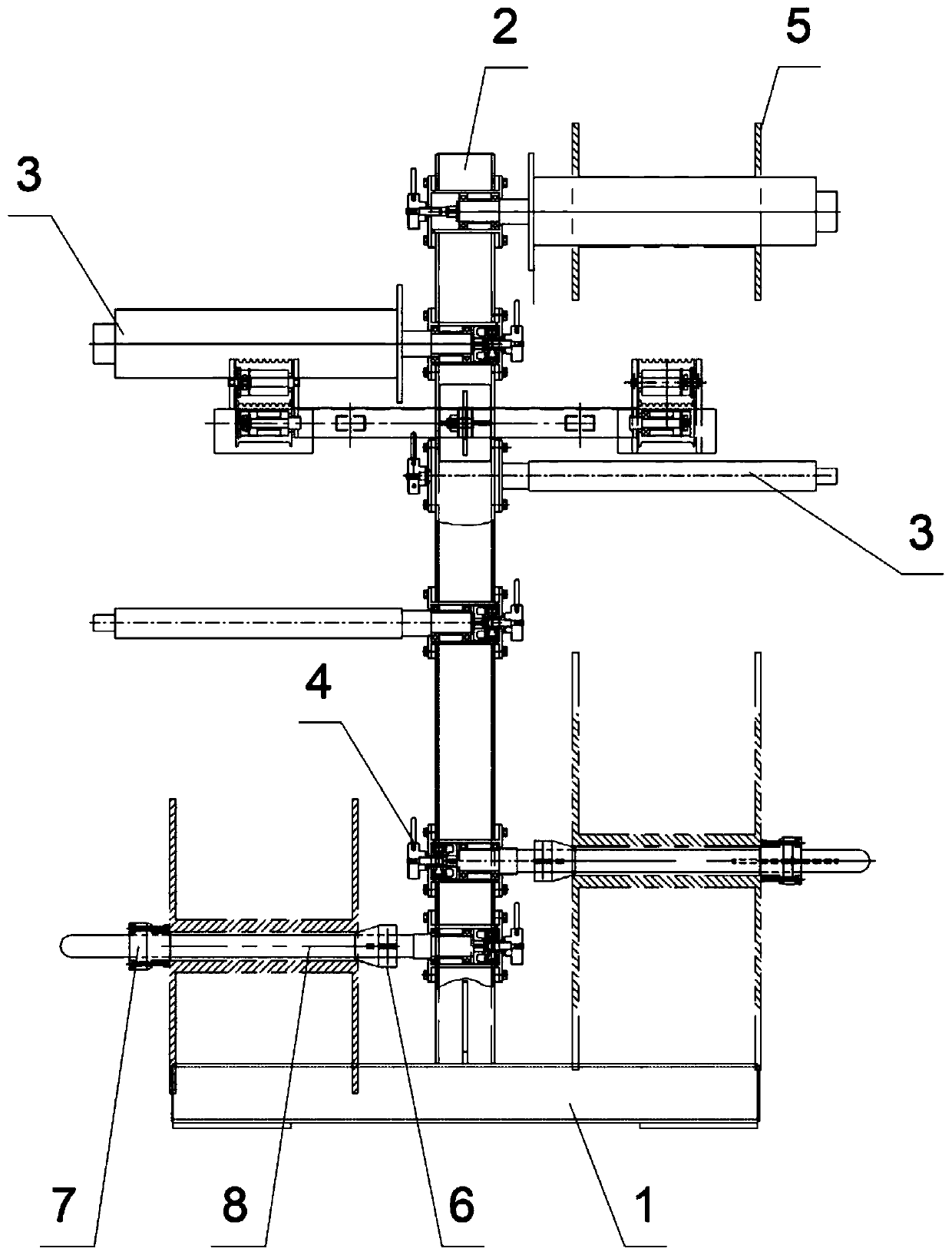
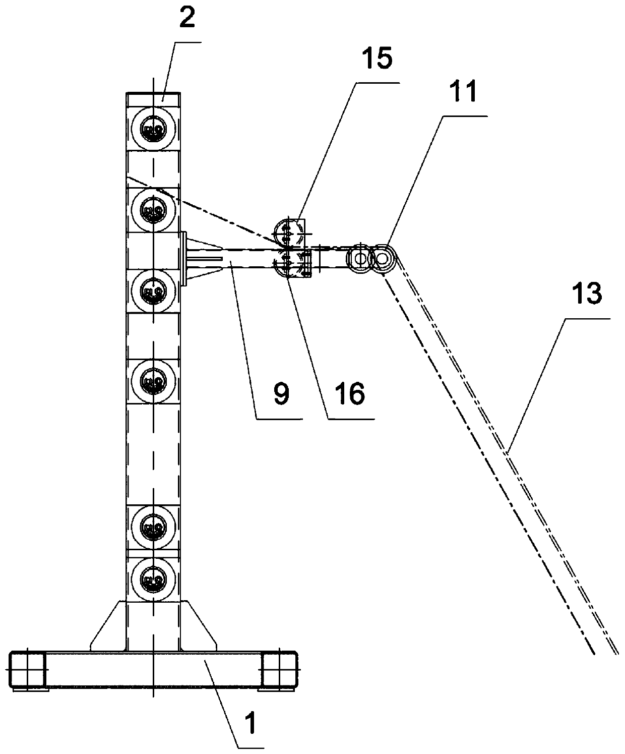
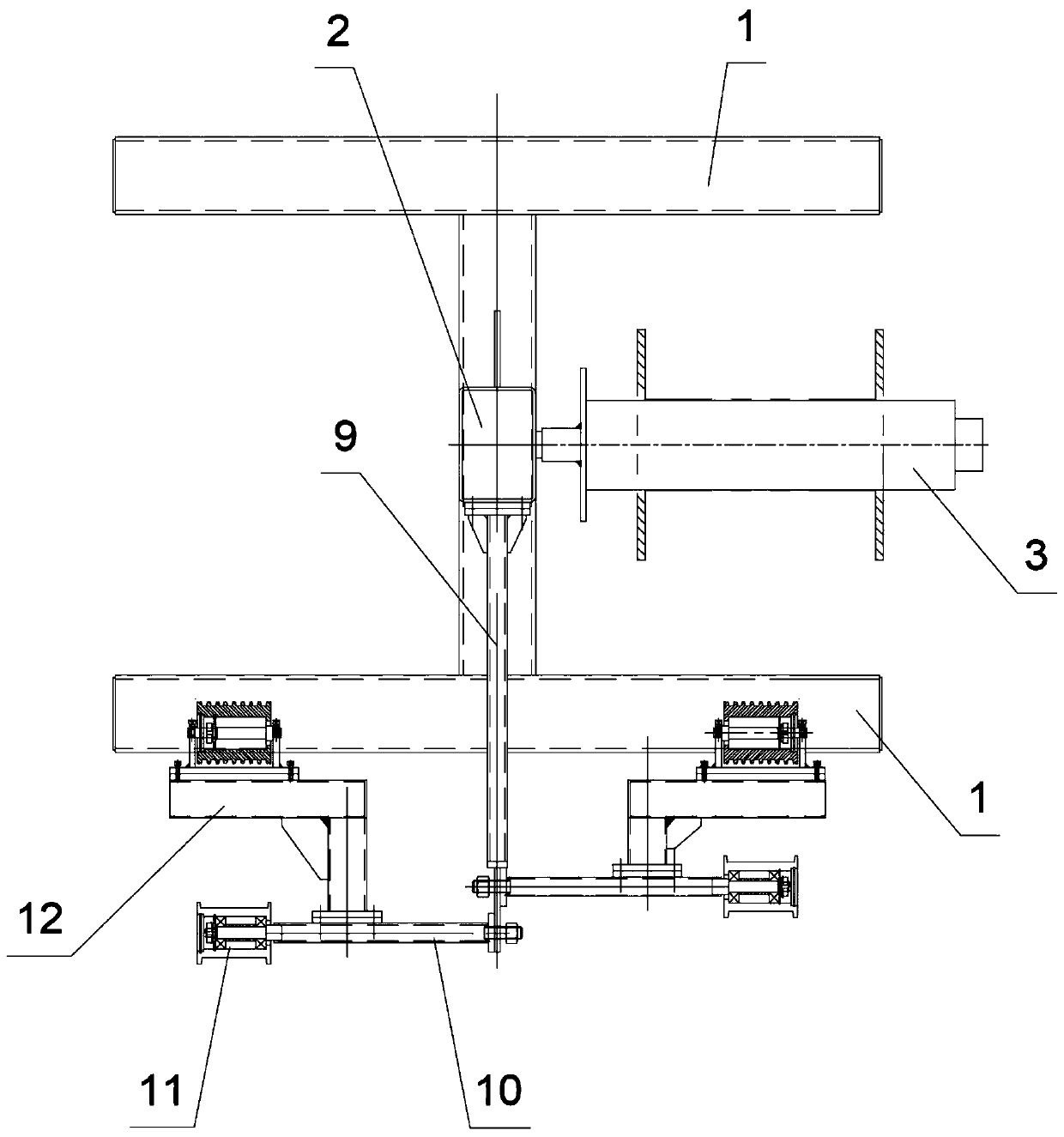
[0029] Such as Figure 1 to Figure 3 As shown, a vertical pay-off frame includes a frame composed of a base 1 and a column 2, on the column 2 there are a plurality of rotating shafts 3 perpendicular to the column 2 for placing cable reels, and the rotating shaft 3 is vertically arranged with the On both sides of the column 2, in this embodiment, there are three on the left side and three on the right side of the column 2, and there is a certain distance between the two rotating shafts 3, which is convenient for placing the cable reel 5. A bearing is arranged between one end of the rotating shaft 3 and the column 2, and a braking device 4 for stopping the rotation of the rotating shaft 3 is arranged at the end of the bearing. Through the above technical solution, the cable reel 5 can be placed on the rotating shaft 3 for off-line operation, which not only saves the storage space of the cable 13, but also facilitates off-line, improves off-line efficiency, and avoids wear and te...

Embodiment 2

[0040] Such as Figure 7 As shown, the difference between this embodiment and the first embodiment lies in that a shaft sleeve corresponding to the inner diameter of the cable reel 5 is sheathed on the rotating shaft 3 . The diameter of the rotating shaft 3 is changed by setting the shaft sleeve, so that the diameter of the rotating shaft 3 and the inner diameter of the cable reel 5 are fixed concentrically, which overcomes the problem caused by the non-concentric rotation of the cable reel and the rotating shaft when the operator pulls the wire during the off-line process. The laborious problem of pulling wires can improve the efficiency of offline.

[0041] The shaft sleeve includes an upper shaft sleeve 24 and a lower shaft sleeve 25. A positioning pin 26 for driving the rotating shaft to rotate is provided on the upper shaft sleeve 24 and / or the lower shaft sleeve 25, and a positioning pin corresponding to the positioning pin 26 is provided on the rotating shaft 3. groove...


PUM


Abstract

The invention relates to a vertical type pay-off rack. The pay-off rack comprises a frame composed of a base and a stand column, multiple rotating shafts which are perpendicular to the stand column and used for containing cable discs are arranged on the stand column, and bearings are arranged between one ends of the rotating shafts and the stand column. Cable storage space is saved, pay-off efficiency is improved, cable wear is avoided, center positioning of inconsistent inner diameters of packaging manners of different cables can be achieved, the problem that in the pay-off process, a workerpulls the cables, and due to non-concentric rotation of the cable discs and the rotating shafts, cable pulling wastes labor can be solved, the pay-off efficiency is improved, a cable guide-out deviceis arranged, the problems of twisting and winding between the cables in the traditional pay-off mode after the cables are pulled out can be solved, the pulled-out cables are smooth and in order, and easy to check and bind, and the pay-off quality is improved.

Description

technical field [0001] The invention relates to a cable offline device, in particular to a vertical pay-off frame. Background technique [0002] In the prior art, it is usually necessary to place the coiled cable on the ground, and the worker pulls the cable to rotate the cable disc. This method will cause frictional damage to the cable and is prone to danger, and the cable is straightened. During the process, multiple groups of cables are easily entangled together. When the cable reel needs to be moved, multiple people are required to pick up the cable reel, which wastes manpower and is very inconvenient to operate. Contents of the invention [0003] The main purpose of the present invention is to solve the technical problems in the prior art and provide a vertical pay-off frame that saves space and improves the efficiency of offline. [0004] For realizing the above object, technical scheme of the present invention is: [0005] A vertical pay-off frame, including a fra...

Claims


Application Information

Patent Timeline
Patent Type & Authority Applications(China)
IPC IPC(8): B65H49/20B65H49/32B65H57/14B65H57/26
CPCB65H49/20B65H49/32B65H49/325B65H57/14B65H57/26B65H2701/30
Inventor 兰军
Owner CSR TIANJIN METRO VEHICLES
Why Eureka
Try Eureka