USB connector structure

a technology of usb connectors and connectors, applied in the direction of flexible/turnable line connectors, coupling device connections, non-rotary current collectors, etc., can solve the problems of limiting the portability, the length of the device, and the structural deficiencies of the foregoing portable wireless receiver b>500/b>, and achieves the effect of small size and convenient portability

Inactive Publication Date: 2006-04-06
INVENTEC CORP
View PDF5 Cites 77 Cited by
  • Summary
  • Abstract
  • Description
  • Claims
  • Application Information

AI Technical Summary

Benefits of technology

[0017] The design provides several advantages. Firstly, by opening a plurality of containing spaces in the body of the connector structure and disposing a plurality of rotating elements, the present invention can integrate a plurality of first or second connectors into the connector structure. Secondly, by disposing a second connector that is capable of free rotation, the body of the connector structure can be freely adjusted to all angles with respect to the second connector that connects to external equipment. Thirdly, by containing the second connector in the containing space or rotating to a certain angel with respect to the body, the first connector or the second connector can

Problems solved by technology

However, the foregoing portable wireless receiver 500 still has structural deficiencies.
Firstly, the USB male connector 100 and the USB female connector 200 respectively installed on the front and back end of the portable wireless receiver 500 undesirably increase the length of the device, thus limiting its portability.
Secondly, there is limited expandability of the portable wireless receiver 500 since the USB male connector 100 and the USB female connector 200 being installed thereon can, at most, connect to two external devices, thereby making the design unab

Method used


Image

  • USB connector structure
  • USB connector structure
  • USB connector structure

Examples


Embodiment Construction

[0034] These and other objects and advantages of the present invention will become more fully apparent from the following detailed description when read in conjunction with the accompanying drawings with like reference numerals indicating corresponding parts throughout for clarity and brevity, wherein:

The First Preferred Embodiment

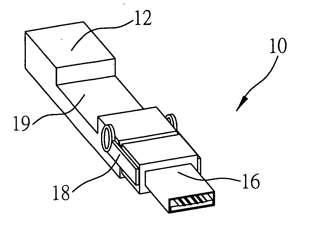
[0035]FIGS. 6A-6C illustrate a connector structure 10 of a first preferred embodiment of the invention comprising: a body 12; a first connector 14 disposed on an end of the body 12; and a pivotal second connector 16 pivotally disposed on the same end of the body 12. Also, the connector structure 10 of the invention can be disposed with a plurality of first connectors 14 or second connectors 16, the detailed description thereof being given in the following preferred embodiments. While this embodiment exemplifies only a first connector 14 and a second connector 16, the actual number of connectors used can vary and is not limited to that as disclosed in thi...


PUM


Abstract

A connector structure is proposed, which includes a body having at least one containing space; at least one first connector being inwardly disposed at one end of the body; at least one second connector being pivotally disposed on the other end of the body, which can be accommodated in the containing space of the body; and at least one rotating element being pivotally connected onto one end of the body, the second connector being fastened onto the rotating element, wherein the rotating element at least has one arm portion, one end of the arm portion being disposed with a pivotal connecting portion which connects to one end of the body. The connector structure further has a switch actuated by the rotation of the pivotal connecting portion of the rotating element thereof, wherein the rotation angle of the switch can control electric conduction of the first connector and the second connector.

Description

BACKGROUND OF THE INVENTION [0001] 1. Field of the Invention [0002] This invention relates to a connector structure, and more particularly, to an improved connector structure having a plurality of connectors. [0003] 2. Description of Related Art [0004] The Universal Serial Bus (USB) standard is a well-known data transmission specification jointly established by IBM, Intel, Microsoft, NEC, Compaq, DEC, and Northern Telecom. Presently, USB is widely utilized to connect equipment with corresponding connectors, such as flash drives, portable hard drives, digital still and video cameras, mice, keyboards, scanners, printers, and so forth. The USB interface possesses a variety of advantages, such as fast data transmission speed, simple and quick connection, Plug-and-Play (PnP) compatibility, lack of an external power-supply, ability to simultaneously support a plurality of devices, excellent compatibility, and so forth, making USB a standard for connecting equipment to personal computers. ...

Claims


Application Information

Patent Timeline
IPC IPC(8): H01R13/44H01R9/03H01R24/58H01R27/00H01R35/04
CPCH01R35/04
Inventor NG, CHONG-KHAIWENG, SHIH-HSIUNG
Owner INVENTEC CORP
Why Eureka
Try Eureka