
Electric generator

A generator and transmission mechanism technology, applied in the direction of electrical components, electromechanical devices, etc., can solve the problems that the generator cannot be used, the external force torque is small, and the internal magnetic field resistance of the generator cannot be overcome, so as to promote the rotation of the rotor, save the torque, and improve the efficiency of the generator. The effect of power generation efficiency

Inactive Publication Date: 2020-01-21
汪忠玉
View PDF0 Cites 1 Cited by
  • Summary
  • Abstract
  • Description
  • Claims
  • Application Information

AI Technical Summary

Problems solved by technology

Different generators have different internal magnetic resistances. Therefore, the selection of external forces needs to take into account the internal magnetic resistance of the generator. However, sometimes the torque of external forces is very small. These external forces cannot drive the generator to rotate, or even overcome the internal magnetic field of the generator. resistance, causing the generator to be unusable

Method used


Image

  • Electric generator
  • Electric generator
  • Electric generator

Examples


Embodiment Construction

[0085] The principles and features of the present invention are described below in conjunction with the accompanying drawings, and the examples given are only used to explain the present invention, and are not intended to limit the scope of the present invention.

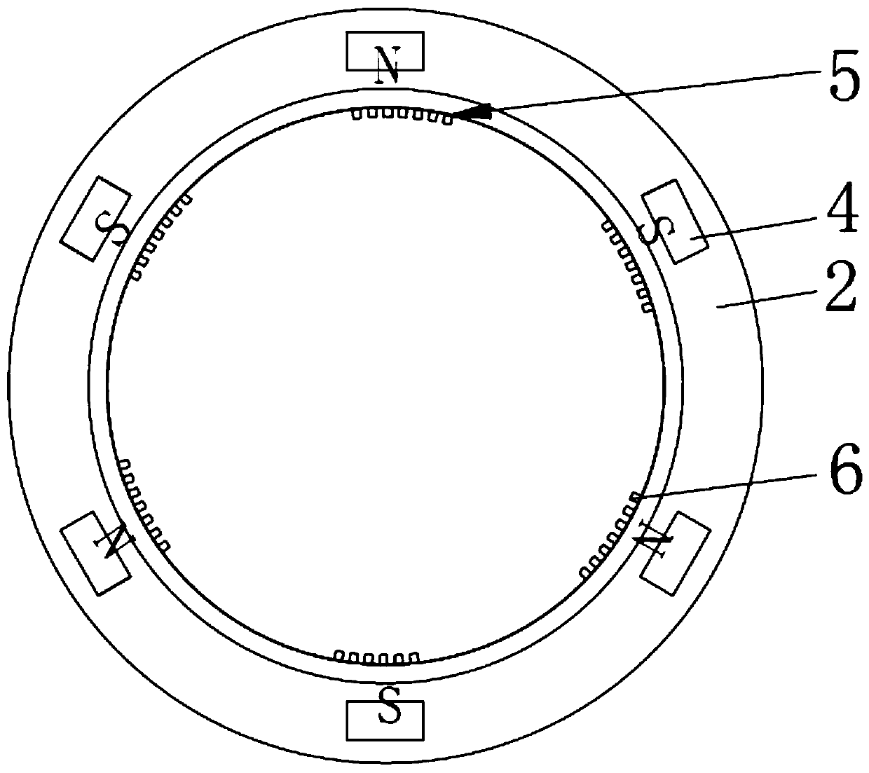
[0086] Such as Figure 1 to Figure 56 as shown, figure 1 It is one of the structural schematic diagrams of the generator provided by the embodiment of the present invention. figure 2 The second schematic diagram of the structure of the generator provided by the embodiment of the present invention. image 3 The third schematic diagram of the structure of the generator provided by the embodiment of the present invention. Figure 4 The fourth schematic diagram of the structure of the generator provided by the embodiment of the present invention. Figure 5 The fifth schematic diagram of the structure of the generator provided by the embodiment of the present invention. Image 6 The sixth schematic diagram of the st...


PUM


Abstract

The invention provides an electric generator. The electric generator comprises a stator, a rotor, a first magnet, a second magnet and a transmission mechanism for driving the first magnet to rotate. The rotor is a cylindrical structure, the rotor is arranged on an outer side of the stator, the first magnet is rotatably arranged at an edge position of one end surface of the stator, the second magnet is arranged on one end surface of the rotor, and the first magnet and the second magnet are arranged on the same plane. And the rotor is in transmission connection with the first magnet through thetransmission mechanism. The rotatable first magnet is arranged on the stator, and rotation of the rotor drives the first magnet to rotate through the transmission mechanism so that a magnetic field direction of the first magnet is changed. Polarity between the first magnet and the next second magnet is changed from original repulsion to attraction. The rotation of the rotor is promoted under an effect of magnetic field attraction, and a magnetic field resistance in the electric generator is reduced.

Description

technical field [0001] The invention relates to the technical field of motors, in particular to a generator. Background technique [0002] As an important core component, generators are widely used in many fields. [0003] In the prior art, when the generator generates electricity, an external force is needed to overcome the magnetic resistance inside the generator and drive the generator to rotate, so as to realize the rotation of the generator and generate electricity. Different generators have different internal magnetic resistances. Therefore, the selection of external forces needs to take into account the internal magnetic resistance of the generator. However, sometimes the torque of external forces is very small. These external forces cannot drive the generator to rotate, or even overcome the internal magnetic field of the generator. resistance, causing the generator to be unusable. Contents of the invention [0004] The technical problem to be solved by the presen...

Claims


Application Information

Patent Timeline
Patent Type & Authority Applications(China)
IPC IPC(8): H02K53/00
CPCH02K53/00
Inventor 汪忠玉汪宪泽
Owner 汪忠玉
Learn More