
Cross-cell mobility method based on asymmetric uplink carrier aggregation

A carrier aggregation and cross-cell technology, which is applied in the field of communication, can solve the problems of not supporting cell switching in asymmetric uplink carrier aggregation scenarios, and inability to perform normal cell switching in asymmetric uplink carrier aggregation scenarios, so as to achieve the effect of normal cell switching

Active Publication Date: 2020-01-21
CHENGDU TD TECH LTD
View PDF6 Cites 1 Cited by
  • Summary
  • Abstract
  • Description
  • Claims
  • Application Information

AI Technical Summary

Problems solved by technology

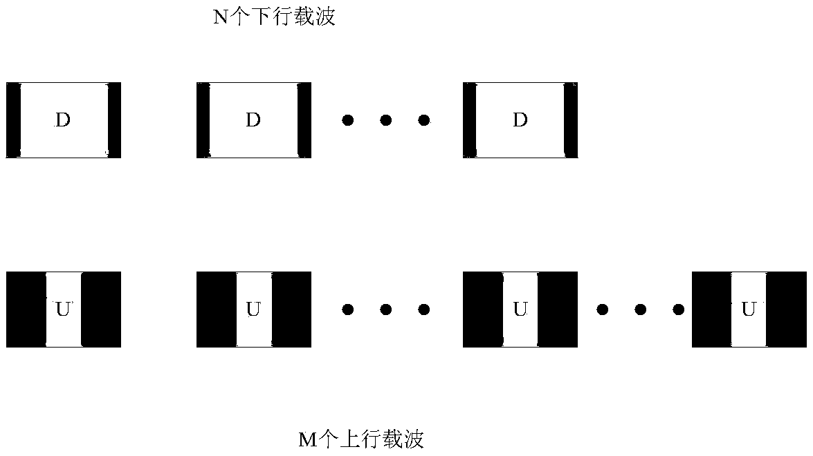
[0015] The current LTE solution only supports cell handover in symmetric carrier aggregation and asymmetric downlink carrier aggregation scenarios, and does not support

Method used


Image

  • Cross-cell mobility method based on asymmetric uplink carrier aggregation
  • Cross-cell mobility method based on asymmetric uplink carrier aggregation
  • Cross-cell mobility method based on asymmetric uplink carrier aggregation

Examples


Embodiment 1

[0101] Figure 6 It is a schematic diagram of the main switching process of Embodiment 1 of the present application, and the process includes the following steps:

[0102] Step 1: The UE judges whether to report the measurement report according to the downlink primary carrier signal quality of the current cell and the adjacent cell, and performs step 2 when it decides to report.

[0103] Step 2: The UE reports a measurement report to the source cell through the uplink primary carrier or secondary carrier.

[0104]Step 3: The source cell judges whether the handover condition is met according to the measurement report. If the handover condition is met, it sends a handover required (Handover Required) message to the MME, and requests the target cell to prepare resources for the handover through the evolved packet core network (EPC). The message carries necessary information, including: handover reason, target cell ID, TAI information and so on.

[0105] Step 4: The core network...

Embodiment 2

[0117] Figure 7 It is a schematic diagram of the main handover process of Embodiment 2 of the present application. The process includes the following steps: Step 1: The UE judges whether to report a measurement report according to the downlink main carrier signal quality of the current cell and the neighboring cell, and when it decides to report, perform step 2.

[0118] Step 2: The UE reports a measurement report to the source cell through the uplink primary carrier or secondary carrier.

[0119] Step 3: The source cell judges whether the handover condition is met according to the measurement report. If the handover condition is met, it sends a Handover Required message to the MME, and requests the target cell to prepare resources for the handover through the EPC. The message carries necessary information, including: handover reason, target cell ID, TAI information and so on.

[0120] Step 4: The core network ECN sends a Handover Request message to the target cell, requesti...


PUM


Abstract

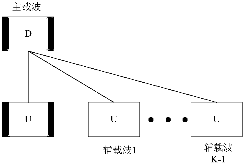
The invention discloses a cross-cell mobility method based on asymmetric uplink carrier aggregation. The cross-cell mobility method comprises the steps that UE judges whether to report a measurement report or not according to downlink main carrier signal quality of a local cell and an adjacent cell; when determining to report, the UE reports a measurement report to a source cell through an uplinkmain carrier or an auxiliary carrier; the source cell sends an RRC connection reconfiguration message to the UE, wherein information carried in the message at least comprises a target cell ID, a maincarrier frequency and main carrier target power; and the UE establishes a main carrier physical resource according to the main carrier frequency and the main carrier target power carried in the RRC connection reconfiguration message, initiates random access on the main carrier of the target cell, and sends an RRC connection reconfiguration completion message. Another method and a system corresponding to the two methods are also provided. By applying the technical scheme disclosed by the invention, cell switching can be realized in an asymmetric uplink carrier aggregation scene.

Description

technical field [0001] The present application relates to the field of communication technologies, and in particular to a method for inter-cell mobility based on asymmetric uplink carrier aggregation. Background technique [0002] In the current LTE system, a single carrier supports a maximum system bandwidth of 20M. To support a larger bandwidth, carrier aggregation technology is required. [0003] In the 3GPP protocol, the aggregation of a maximum of 5 carriers is supported, but the number of downlink carriers is required to be greater than or equal to the number of uplink carriers. In the public network operator's network, the downlink service requirements are generally greater than the uplink service requirements, and the carrier aggregation defined by 3GPP can better meet the operator's network. [0004] However, in some industrial network applications, there will be a large number of video surveillance services. At this time, the demand for uplink services is greater ...

Claims


Application Information

Patent Timeline
IPC IPC(8): H04W24/10H04W36/00H04W74/08
CPCH04W24/10H04W36/0088H04W36/0016H04W74/0833
Inventor 鲜柯徐绍君黄伟
Owner CHENGDU TD TECH LTD
Learn More