

Dust collection device and air conditioner
A kind of dust collection equipment and dust collection technology, applied in air conditioning system, lighting and heating equipment, space heating and ventilation, etc., can solve problems such as difficult operation, and achieve the effect of improving particle collection rate
- Summary
- Abstract
- Description
- Claims
- Application Information
AI Technical Summary
Problems solved by technology
Method used
Image

Examples
Embodiment approach 1
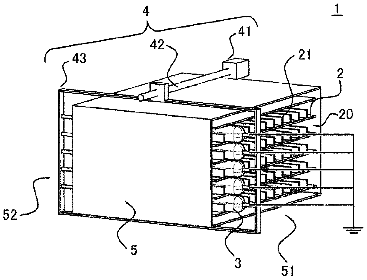
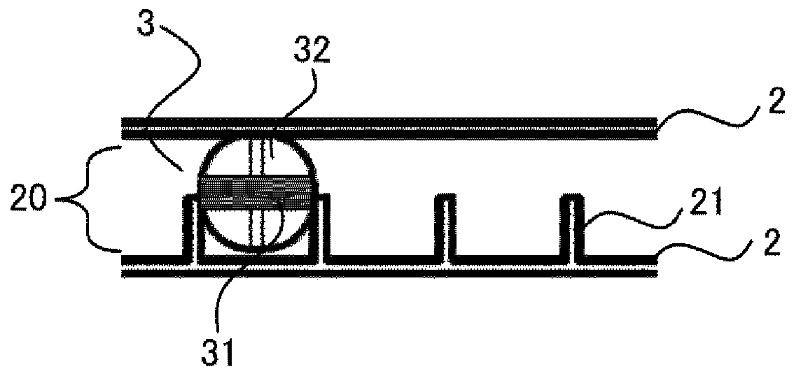
[0031] figure 1 A schematic diagram showing the dust collection equipment of Embodiment 1 of the present invention. In addition, figure 2 Indicates its main part.
[0032] The dust collection device 1 includes: a plurality of dust collection bodies 2; a friction body 3 that rubs the dust collection body 2 to charge static electricity; a frame body composed of an outer frame 5 covering them; and holds the friction body 3 The driving part 4 frictionally moves along the outer surface of the dust collecting body 2.
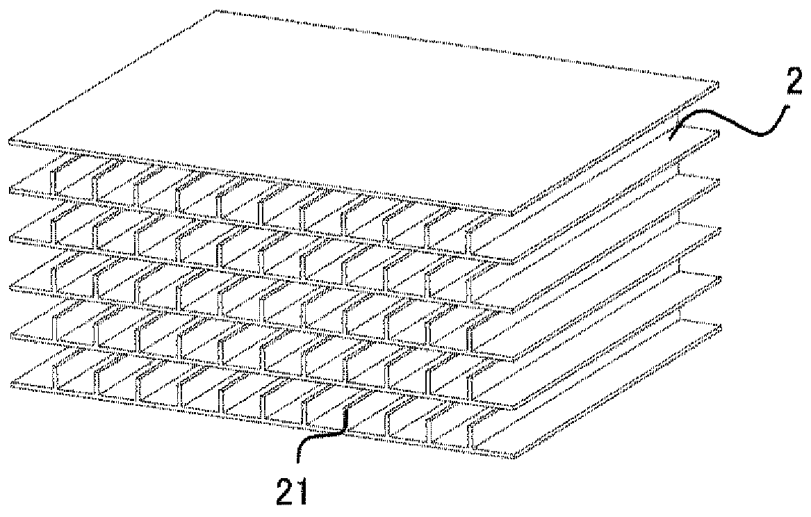
[0033] The plurality of dust collecting bodies 2 are arranged at intervals with each other so as to form an air passage 20 between adjacent dust collecting bodies 2. That is, the dust collecting body 2 is arranged facing each other across the air duct 20. In addition, the outer shell 5 includes an inflow port 51 through which air flows in and an outflow port 52 through which air that has passed through the air passage 20 flows out. The air containing particles to be tr...
Embodiment approach 2
[0062] In the dust collecting facility of the second embodiment, the structure of the dust collecting body 2 is different from that of the first embodiment, and is the same as the first embodiment except for this. Hereinafter, the description will focus on the differences.
[0063] Figure 7 The main part of the dust collector of Embodiment 2 is shown. The dust collecting device of the second embodiment includes a first dust collecting body 22 and a second dust collecting body 23 as the dust collecting body 2. The first dust collecting body 22 is positively charged by friction with the friction body 3. The second dust collecting body 23 is negatively charged. One of the dust collecting bodies 2 arranged facing each other is the first dust collecting body 22 and the other is the second dust collecting body 23. A polyamide (PA6) with a strong tendency to be positively charged by friction is cited as an example of the positively charged first dust collector 22, and a polypropylene...
Embodiment approach 3
[0074] In the dust collector of the third embodiment, the structure of the friction body 3 is different from that of the first embodiment, and is the same as the first embodiment except for this. Hereinafter, the description will focus on the differences.
[0075] Picture 8 The main part of the dust collection device of Embodiment 3 is shown. In the dust collection device of the third embodiment, the friction body 3 includes a first friction material 33 that is negatively charged by friction with the dust collection body 2 and a second friction material 34 that is positively charged. The first friction material 33 and the second friction material 34 are arranged such that one of the dust collectors 2 facing each other across the air passage 20 is rubbed by the first friction material 33 and the other is rubbed by the friction material 34. In addition, when one dust collecting body 2 is sandwiched by a plurality of friction bodies and rubbed, one dust collecting body 2 is rubbed...
PUM
 Abstract
Description
Claims
Application Information