

Dust collection equipment and air conditioner
A dust collection equipment and dust collection technology, applied in air conditioning systems, lighting and heating equipment, space heating and ventilation, etc., can solve problems such as difficult operation, and achieve the effect of improving particle capture rate
- Summary
- Abstract
- Description
- Claims
- Application Information
AI Technical Summary
Problems solved by technology
Method used
Image

Examples
Embodiment approach 1
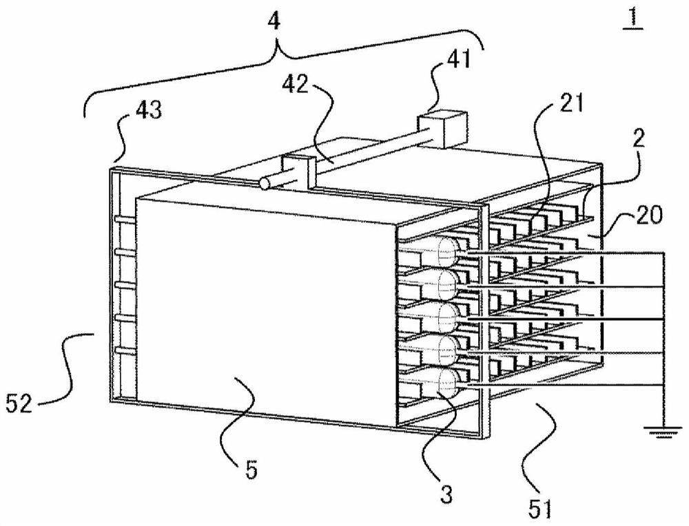
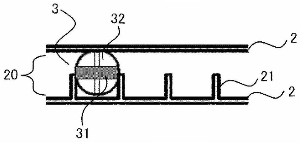
[0031] figure 1 It is a schematic diagram which shows the dust collector of Embodiment 1 of this invention. in addition, figure 2 Indicates its main part.
[0032] The dust collecting equipment 1 is equipped with: a plurality of dust collecting bodies 2; friction bodies 3 which rub against the dust collecting bodies 2 to make it electrostatically charged; a frame body made of an outer shell 5 covering them; and holding the friction bodies 3 and making them The driving part 4 frictionally moves along the outer surface of the dust collector 2 .
[0033] A plurality of dust collectors 2 are arranged at intervals so as to form air passages 20 between adjacent dust collectors 2 . That is, the dust collectors 2 are arranged to face each other across the air duct 20 . In addition, the housing 5 includes an inlet 51 through which air flows in and an outlet 52 through which air passing through the air passage 20 flows out. The air containing particles to be captured flows in from...
Embodiment approach 2
[0062] In the dust collection facility of Embodiment 2, the structure of the dust collector 2 differs from Embodiment 1, and is the same as Embodiment 1 except that. Hereinafter, the difference will be mainly explained.
[0063] Figure 7 The main part of the dust collection facility of Embodiment 2 is shown. The dust collecting device according to the second embodiment includes a first dust collecting body 22 and a second dust collecting body 23 as the dust collecting body 2, the first dust collecting body 22 is positively charged by friction with the friction body 3, and the The second dust collector 23 is negatively charged. One of the dust collectors 2 arranged facing each other is the first dust collector 22 , and the other is the second dust collector 23 . Enumerate polyamide (PA6) with strong triboelectric charge tendency as an example of the positively charged first dust collector 22, and enumerate polypropylene (PP) with strong triboelectric charge tendency as the ...
Embodiment approach 3
[0074] In the dust collector of Embodiment 3, the structure of the friction body 3 differs from Embodiment 1, and is the same as Embodiment 1 except that. Hereinafter, the difference will be mainly explained.
[0075] Figure 8 The main part of the dust collection facility of Embodiment 3 is shown. In the dust collecting facility of Embodiment 3, the friction body 3 is provided with the 1st friction material 33 negatively charged by friction with the dust collector 2, and the 2nd friction material 34 positively charged. The first friction material 33 and the second friction material 34 are arranged such that the first friction material 33 rubs one of the dust collectors 2 facing each other across the air duct 20 , and the friction material 34 rubs the other. Moreover, when rubbing one dust collecting body 2 between several friction bodies, one dust collecting body 2 is rubbed by the same kind of friction material. in addition, Figure 8 In the figure, the structure in whic...
PUM
 Abstract
Description
Claims
Application Information