A Fixing Device for Adjustable Pipeline Flux Leakage Detection Probe

A technology of magnetic flux leakage detection and fixing device, which is applied in the direction of pipeline system, machine/support, supporting machine, etc., can solve the problems of inconvenient use, inaccurate detection results, and the detection probe cannot detect pipelines, and achieves the reduction of friction, The effect of increasing the detection range and saving power consumption

Active Publication Date: 2021-03-09
浙江越新检测技术有限公司
View PDF10 Cites 0 Cited by
  • Summary
  • Abstract
  • Description
  • Claims
  • Application Information

AI Technical Summary

Problems solved by technology

[0002] Even if multiple detection probes are installed in the currently used fixing device for the detection probe, it cannot perform a comprehensive detection of the pipeline, and cannot automatically adjust the position of the detection probe on the pipeline. It is necessary to manually rotate the probe to detect various parts of the pipeline, which is very difficult to use. Inconvenient, and the detection probe can not be very close to the pipeline, resulting in inaccurate detection results

Method used


Image

  • A Fixing Device for Adjustable Pipeline Flux Leakage Detection Probe
  • A Fixing Device for Adjustable Pipeline Flux Leakage Detection Probe
  • A Fixing Device for Adjustable Pipeline Flux Leakage Detection Probe

Examples


Embodiment 1

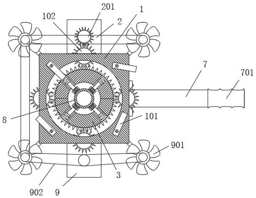
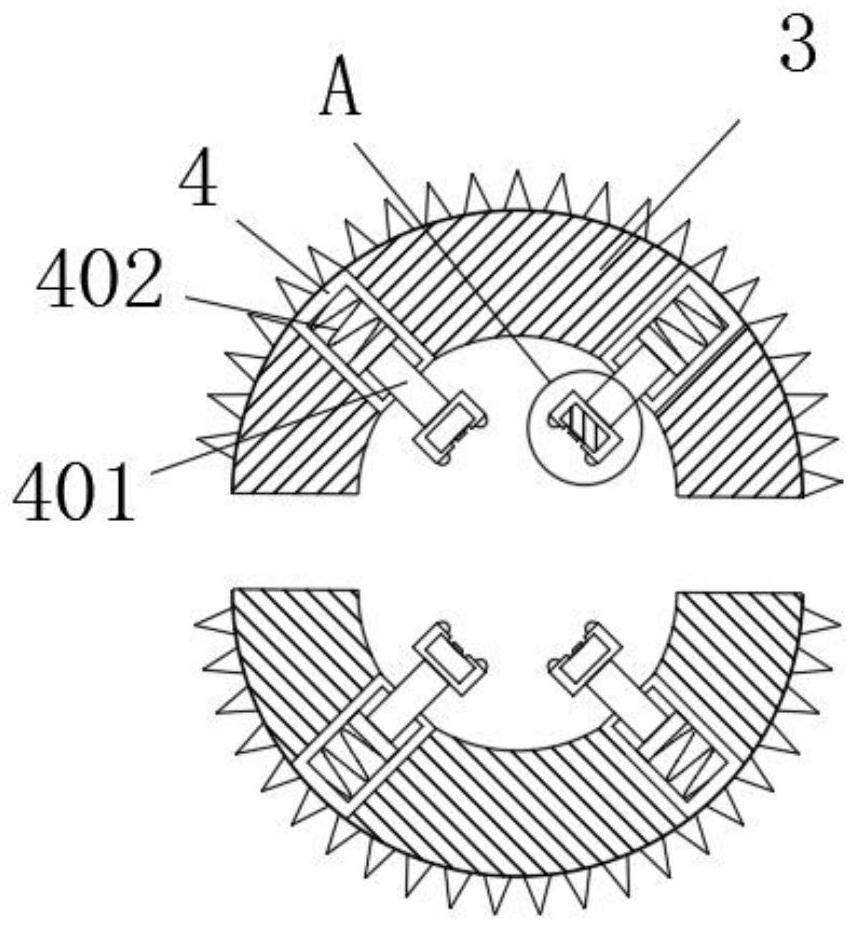
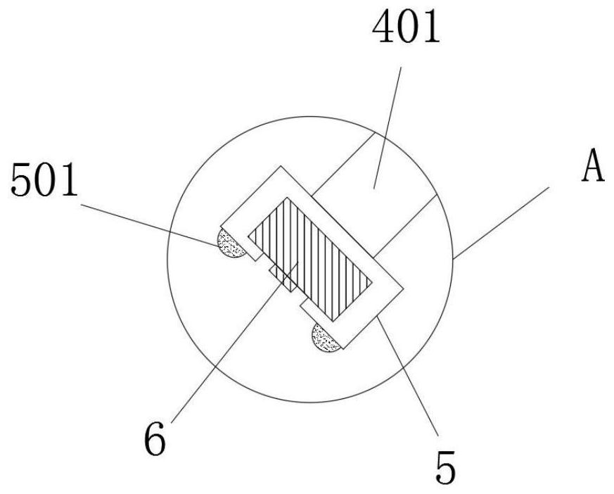
[0021] see Figure 1-2 , a fixing device for an adjustable pipeline magnetic flux leakage detection probe, comprising an outer casing 1 and a rotating detection mechanism installed inside the outer casing 1 for detecting magnetic flux leakage of a pipeline 8 and a rotating detection mechanism arranged on the outer casing 1 for supporting the rotating detection mechanism The second gear 102, the rotation detection mechanism includes a semi-circular ring 3, the interior of the semi-circular ring 3 is inlaid with a limit block 4, the limit block 4 is provided with a chute, and the sliding card in the chute is provided with a slider 401 , one end of the slider 401 is elastically connected to the bottom of the limit block 4 through a spring, and the other end of the slider 401 is fixedly installed with the installation block 5, please refer to image 3 , the installation block 5 is provided with an installation groove and an opening is provided on the installation block 5, a magnet...

Embodiment 2

[0029] In order to facilitate the application of this device to detect pipelines in water, this embodiment has been further improved on the basis of embodiment 1. Compared with embodiment 1, the main difference is that: the outer jacket 1 is also provided with a second Two drive motors 9 and fan blades 901, the second drive motor 9 is fixedly installed on the overcoat 1, the second drive motor 9 and the fan blades 901 are connected by belt transmission, after the device is sleeved on the pipeline 8 in the water, Start the second drive motor 9 to drive the fan blade 901 to rotate, which can drive the device to move along the pipeline 8. At the same time, the device will rotate on the pipeline 8 during the movement of the device driven by the fan blade 901, so there is no need to start the first A drive motor 2 drives the rotation detection mechanism to rotate, saving power consumption.

[0030] The installation number and installation position of the fan blades 901 on the outer...


PUM


Abstract

The invention discloses a fixing device for an adjustable pipeline magnetic flux leakage detection probe, which includes a jacket, a rotation detection mechanism and a second gear. In the jacket, start the first motor, drive the magnetic flux leakage detector on the rotation detection mechanism to rotate through the first gear and the second gear, increase the detection range of the device, set the ball, reduce the friction when moving the device, and slide The elastic connection between the block and the bottom of the limit block makes the magnetic flux leakage detector better close to the surface of the pipeline, and is suitable for detecting pipelines with different diameters. The device is set on the pipeline in the water and starts the second drive motor Driving the fan blades to rotate can drive the device to move along the pipeline. At the same time, because the fan blades drive the device to move, the device will rotate on the pipeline, so there is no need to drive the rotation detection mechanism to rotate by starting the first driving motor.

Description

technical field [0001] The invention relates to a fixing device, in particular to a fixing device for an adjustable pipeline magnetic flux leakage detection probe. Background technique [0002] Even if multiple detection probes are installed in the currently used fixing device for detection probes, the pipeline cannot be fully detected, and the position of the detection probes on the pipeline cannot be automatically adjusted. It is necessary to manually rotate the probes to detect various parts of the pipeline, which is very difficult to use. It is inconvenient, and the detection probe cannot be well close to the pipeline, resulting in inaccurate detection results. Contents of the invention [0003] The object of the present invention is to provide a fixing device for an adjustable pipeline magnetic flux leakage detection probe, so as to solve the problems raised in the above-mentioned background technology. [0004] To achieve the above object, the present invention prov...

Claims


Application Information

Patent Timeline
Patent Type & Authority Patents(China)
IPC IPC(8): F16M13/02F16M11/04F16M11/42F17D5/02
CPCF16M11/04F16M11/425F16M13/02F17D5/02
Inventor 金杭飞
Owner 浙江越新检测技术有限公司
Why Eureka
Try Eureka